background image

Valves, co systems

Operating instructions 

EN

Electromotive actuator  

„Aktor M ST L Modbus“, 24 V, (DN 40/50)

Содержание Aktor M ST L Modbus

Страница 1: ...Valves controls systems Operating instructions EN Electromotive actuator Aktor M ST L Modbus 24 V DN 40 50...

Страница 2: ......

Страница 3: ...3 Availability of the operating instructions 6 3 Technical description 7 3 1 Construction 7 3 2 Functional description 7 3 2 1 Basic functions 7 3 2 2 Calculation functions 8 3 2 3 Limitation function...

Страница 4: ...1 2019 6 3 2 Via the Modbus parametrization 13 6 4 Manual operation 13 6 4 1 Extending the drive stem 13 6 4 2 Retracting the drive stem 14 7 Maintenance 14 8 Removal 14 9 Disposal 14 10 Appendix 15 1...

Страница 5: ...le connec tions 1 3 Extent of supply Electromotive actuator Aktor M ST L Modbus 24 V Operating instructions 1 4 Contact Address OVENTROP GmbH Co KG Paul Oventrop Stra e 1 59939 Olsberg GERMANY Technic...

Страница 6: ...s injury if not avoided CAUTION Indicates a possible danger with lower risk The situation may lead to minor and revers ible injury if not avoided NOTICE Indicates a situation that may lead to damage t...

Страница 7: ...e actuator is operated with steady control The control signal 0 100 is transmitted via Modbus communication The current position 0 100 can be queried via Modbus Valve anti blocking function The actuat...

Страница 8: ...d via Modbus and the calculated current output When exceeded the volume flow will be reduced until the limit value is reached again 3 2 4 Control function Output control registers 130 200 301 310 311...

Страница 9: ...s Permissible fluid temperature in the valve 0 120 C Ambient tempera ture 0 50 C Ambient humidity In operation 0 85 r h not condensing Out of operation 0 85 r h not condensing Overvoltage cate gory De...

Страница 10: ...ches Bit 1 bis 6 are set to OFF see section 5 3 1 on page 12 5 1 Fitting of the actuator Make sure that there is enough space for the installation of the actuator The actuator must only be connected t...

Страница 11: ...e to dripping water f Do not feed the cable in from the top 1 Remove the casing cover 2 Connect the data lines for the Modbus and if required the lines for the universal inputs according to the assign...

Страница 12: ...D is located under the casing cover above the terminal on the right hand side and dis plays the operating status of the actuator The status LED is visible even when the cover is closed Status LED Mean...

Страница 13: ...error message will be gen erated again immediately 5 Baud rate change The currently set parameters of the register addresses 105 107 are applied 6 4 Manual operation The manual mode is only intended...

Страница 14: ...Disconnect all electrical connections 4 Press the push button to release the latched valve stem position 1 in Illust 2 on page 7 5 Unscrew the collar nut 6 Remove the actuator from the valve Also remo...

Страница 15: ...1 23 2 uint16 HW identifier r e g 0x00F1 3 uint16 SerNum1 r 0 65535 4 uint16 SerNum2 r 0 65535 5 uint16 SerNum3 r 0 65535 101 uint16 Time hour r w 0 23 to be set manually no battery buffered RTC 102...

Страница 16: ...input 3 KP10 4 NI1000_DIN 5 NI1000_LG 6 PT1000 8 Y output 0 10V register 426 9 Y feedback 0 10V register 401 10 Change over output 0V cooling 5V shut off 10V heating 127 uint16 Inversion P2 input r w...

Страница 17: ...ure control according to register differential temperature 201 uint16 Change over mode r w 0 Shut off 1 Heating 2 Cooling 3 Automatic according to flow temperature 300 uint16 Nominal value room temper...

Страница 18: ...w Current flow temperature in C 10 write protected in case of assigned source P1 or P2 405 int16 Return temperature r w Current return temperature in C 10 write protected in case of assigned source P...

Страница 19: ......

Страница 20: ...OVENTROP GmbH Co KG Paul Oventrop Stra e 1 59939 Olsberg GERMANY www oventrop com 101274584 V01 11 2019...
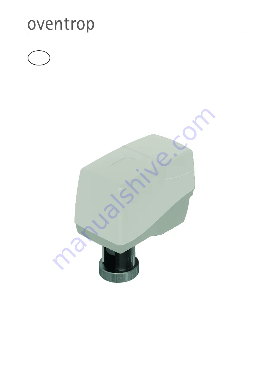
Отзывы: