


1 5
TRM138
3.2.6.7. The DAC shall be powered from an independent direct current source providing
galvanic insulation of the instrument’s and the user’s electrical circuit. Power source voltage is
determined by the formulas:
U
ps/min
< U
ps/nom
< U
ps/max
;
U
ps/min
= 7.5 + I
CAD max
R
load
;
U
ps/max
= U
ps/min
+ 2.5,
where: U
ps/nom
– power source nominal voltage, V;
U
ps/min
– power source minimal admissible voltage, V;
U
ps/max
– power source maximal admissible voltage, V;
I
CAD max
– DAC maximum output current, mA;
R
load
– DAC load resistance, kOhm.
If on whatever reason pressure the DAC’s power source voltage exceeds design value U
ps/max
than in series with the load a limit resistor shall be installed whose resistance is calculates by the
formulas:
R
lim/min
< R
lim/nom
< R
lim/max
;
R
lim/min
= U
ps
– U
ps/max
R
lim/max
= U
ps
– U
ps/min
I
DAC/max
I
DAC/max
Where: R
lim/nom
– limit resistor nominal value, kOhm;
R
lim/min
– limit resistor minimal admissible value, kOhm;
R
lim/max
– limit resistor maximal admissible value, kOhm;
I
DAC/max
– DAC maximum output current, mA;
U
ps
– DAC power source voltage, V.
ATTENTION!
The DAC’s power source voltage shall not exceed 30 V.
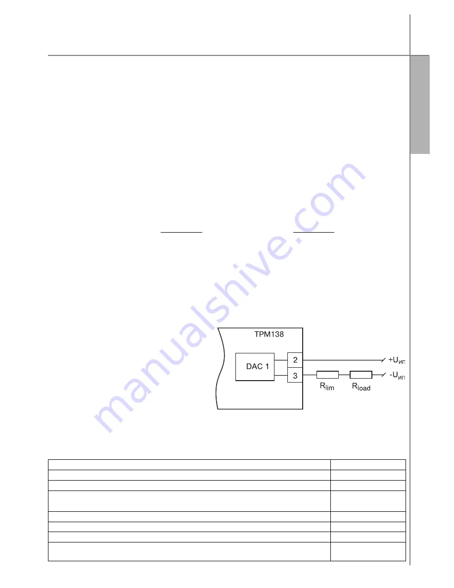
An example of the DAC’s connection to the power source and the load is
presented on Figure 14.
To power the DAC, a builtin direct
current source for 24 V not used for active
sensors can be applied. When a builtin
power source is used, the above requirements
shall be complied with.
3.2.7 Emergency Alarm and Warning
3.2.7.1. The instrument monitors
operability of primary converters connected
to it and at fault of any of them generates a
signal
“Sensor fault”
displaying on the
digital indicator messages on the fault
(description of the messages and their
reasons are presented in Table 5).
Table 5
Fault cause
Message on DI2
RTT short circuit
0.0.0.0.
RTT or TC rupture
RTT, TC or active sensor falling beyond the lower limit of the control range
(except for types 11, 12, 13 as per Table A3.2)
LLLL
RTT, TC or active sensor falling beyond the upper limit of the control range
НННН
TC’s tails overheating
OtCL
Measuring device fault
AdEr
Sensor number preset in
С.in (PL2)
parameter is disabled program
matically by setting
int (PL2) = oFF
in.oF
Section 3
Instrument Design and Operation
Figure 14. The DAC / load
connection diagram
Содержание TPM138
Страница 23: ...22 TRM138 Setting up Procedures Section 6 Figure 16 Programmed parameters setting diagram...
Страница 24: ...23 TRM138 Section 6 Setting up Procedures...
Страница 30: ...29 TRM138 Appendix 1 Dimensional drawing...
Страница 31: ...30 TRM138 Instrument connection Appendix 2 Figure A2 1 Instrument terminal block contacts arrangement diagram...
Страница 35: ...34 TRM138 Figure A2 10 Example of connection of various type transducers Instrument connection Appendix 2...


