


9
TRM138
Section 3
Instrument Design and Operation
Example.
The interrogation list includes sensing transducers:
d1 (8), d3 (7), d4 (7), d5 (6),
d6 (6) and d8 (5)
with appropriate priority values (in brackets). The transducers will be interrogated
in the following order:
d1– d3 – d1 – d4 – d1– d5 – d1 – d3 – d1 – d4 – d1– d6 – d1 – d8
and
so on by the cycle.
Note.
The interrogation algorithm with set priority values makes it possible for the user to increase frequency of
interrogation for those sensing transducers which are related to rapidly changing physical properties
thus ensuring the fastest response for their output equipment. However, it is to bear in mind that increase
in interrogation frequency of one sensing transducers shall decrease interrogation frequency of othertrans
ducers.
3.2.2.3 Input Parameters Running Values Measuring
3.2.2.3.1 Signals of sensing transducers from
AC1
automatic commutation device are
transmitted to the MD measuring device entry. The MD evaluates running values of controlled
physical properties and digitizes them to provide for their further processing.
3.2.2.3.2 When resistive temperature transducers and thermocouples are used temperature
is computed by
standard NSCs
.
The instrument’s readings are automatically adjusted by temperature of
thermocouples’ tails
. The adjustment procedure is disabled (for example, at calibration of the
instrument) by setting
Cj.C (PL0)
parameter to
oFF
.
3.2.2.3.3 When active converters (sensing transducer types “06”, “10”, “11”, “12” or “13” in
Table A3.2) are used controlled parameters’ values are computed directly in their measuring units.
Adjusting coefficients are set for each sensing transducer at identification of
Ain.L (PL1)
parameters – the lower measurement limit and
AinH (PL1)
– the upper measurement limit.
3.2.2.4 Measurements Digital Filtering
3.2.2.4.1 To reduce impact of environmental impulse noise on the instrument’s operating
performance measurements independent digital filtering is provided for each measuring channel.
The filtering is made in two stages.
3.2.2.4.2 For the first stage the user sets “filter strip”
in.FG (PL1)
parameter individually
for each sensing transducer in measuring units of measured physical values. This filter is disabled
by setting
0
value in
in.FG (PL1)
parameter.
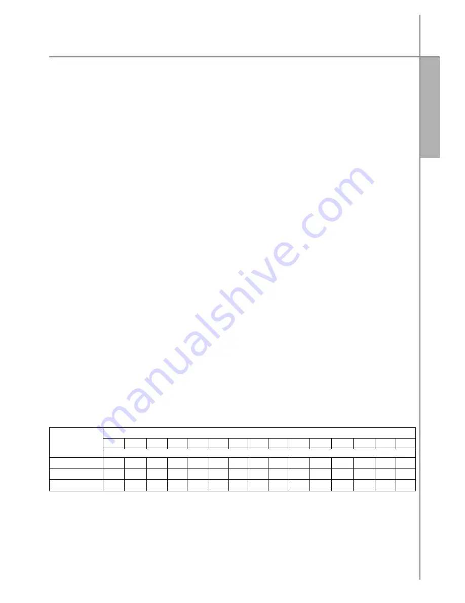
3.2.2.4.3 For the second stage of filtering the user sets “filter time response” parameter –
in.Fd (PL1).
ATTENTION!
Increase in
in.Fd (PL1)
parameter value provides for a better
noninterference of the measuring channel but simultaneously increases its time lag, i.e.,
reduces the instrument’s response to rapid changes of an input value. The instrument’s
response to abrupt change in arrival signal from 0.0 to 10.0% of the measured range at various
in.Fd (PL1)
values is presented in Table 4 (
in.FG
filter isdisabled).
Table 4
Filter time response
in.Fd
1 2 3 4 5 6 7 8 9 10 11 12 13 14 15
Number of measurements required to reach the level
7,0
2 3 5 6 7 8 9 11 12 13 14 16 17 18 19
9,0
4 6 8 11 13 15 18 20 23 25 27 29 31 34 36
9,5
5 8 11 14 18 20 23 26 29 32 35 38 41 44 46
This filter is disabled by setting
0
value in
in.Fd (PL1)
parameter.
Measured
value (level)
Содержание TPM138
Страница 23: ...22 TRM138 Setting up Procedures Section 6 Figure 16 Programmed parameters setting diagram...
Страница 24: ...23 TRM138 Section 6 Setting up Procedures...
Страница 30: ...29 TRM138 Appendix 1 Dimensional drawing...
Страница 31: ...30 TRM138 Instrument connection Appendix 2 Figure A2 1 Instrument terminal block contacts arrangement diagram...
Страница 35: ...34 TRM138 Figure A2 10 Example of connection of various type transducers Instrument connection Appendix 2...


