B-526-10N-E
33
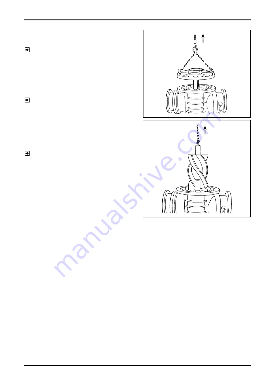
(2) Using the eyebolts (119) furnished, hoist the front
cover (102) horizontally by a wheel crane, or
similar equipment and remove it.
NOTE:
Be careful to avoid bumping the thrust
rings (223) and (224) against hard objects.
(3) Remove rotors (201 and 202). To do this, screw in
eyebolts into the end face of rotor shaft (203),
hoist it by a wheel crane, or similar equipment
and, carefully turning it according to the spiral
gear teeth, extract it.
NOTE:
Thrust rings (223 and 224) are attached
to the rotor shafts. Exercise care to avoid
bumping them, especially the lower one,
against the rear cover.
(4) The measuring chamber is now accessible for
inspection. Thoroughly clean the rotors,
measuring chamber and covers with cleaning oil,
using care to keep grit and grime out.
NOTE:
See page 30 for the procedure to recon-
dition rotor gear teeth.
HOIST
HOIST
3. Rear Bearing Assembly
Following the procedures in Sections 1 and 2 , follow the steps below:
(1) Place the flowmeter body upside down with the rear cover (103) up. Apply suitable blocks below the meter
body and place on a level surface, observing the CAUTION in step (5) on page 28.
(2) Remove blind cover (105).
(3) Extract the bearing holder (208). To do this, use the tapped holes provided for extracting the bearing holder.
Careful attention must be paid to the O-ring (211) attached to the bearing holder.
Содержание ULTRA UF-II
Страница 67: ...B 526 10N E 67...


