background image

11

1 pc. plug pull-off protection

1 pc. No Carbon Zone sticker

1 pc. Instructions for use (qualified personnel) 

1 pc. Instructions for use (user) 

Accessories

3 pc - 8 pc 13E400=*/13E401=* Remote electrodes

The remote electrodes can be combined with any of the following electrode domes:

13Z161 electrode dome, flat 

 (6 pc. per package)

or

13Z162 electrode dome, medium 

 (6 pc. per package)

or

13Z163 electrode dome, high 

 (6 pc. per package)

Myo Plus app

6 Charging the battery

We recommend charging on a daily basis. If the device is not used for an extended period, the
battery charge level should be checked regularly and the battery recharged.
See the respective instructions for use for information on correct battery charging.

7 Preparing the product for use

7.1 Laminating instructions

The product can be positioned in the forearm socket.

7.2 Determine electrode position

INFORMATION

Depending  on  the  residual  limb  and  socket  structure,  the  electrode  domes  may  leave  impres­
sions in the patient's skin. Use the flat electrode domes in case of deep impressions in the skin.
Use the high electrode domes if there are no or only barely visible impressions in the patient's
skin.

Required tools

Drill; twist drill ø 5 mm

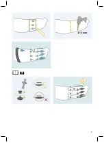
The remote electrodes have to be positioned as follows:
1)  Mark the position of remote electrode 1 below the ulna and 6-7 cm distal of the olecranon.
2)  Extend the marking around the entire circumference of the prosthetic socket.

This creates a circumferential line.

3)  From the line, measure and mark 40 mm in the distal direction.
4)  Extend the marking around the entire circumference of the prosthetic socket.

This creates a second circumferential line.

5)  Determine  the  positions  of  the  remaining  remote  electrodes  using  the  positioning  gauge  for

the O&P professional.

6)  Mark the remote electrodes 2 - 8 on the proximal line (e.g. with an X).
7)  Reflect the electrode positions to the distal line.
8)  Drill through the prosthetic socket at the marked locations with a 5 mm bit.
9)  For 2 of 8 electrodes, an additional hole has to be drilled for the reference potential contact.

INFORMATION:  The  hole  for  the  reference  potential  contact  can  either  be  drilled
between the two electrode domes or in a position where little muscle activity is expec­
ted.

The electrode dummies must be used to fabricate the outer socket. The battery dummies and Myo
Plus  TR  dummy  must  be  positioned  on  the  prosthetic  socket  according  to  the  space  require­
ments. If desired, the remote electrodes can also be attached in the cavity between the outer and

Содержание Myo Plus

Страница 1: ...Instructions for use qualified personnel 5 Myo Plus...

Страница 2: ...the instructions for use Angewandte Symbole Symbole Used Symboles utilis s Simboli utilizzati S mbolos utilizados S mbolos utilizados Gebruikte symbolen Symboler som anv nds Anvendte symboler Benytted...

Страница 3: ...3...

Страница 4: ...1 2 3 4 5 7 8 6 1 2 3 4 5 7 8 6 1 2 3 13E190 4...

Страница 5: ...ly put the product into use in accordance with the information contained in the accompanying documents supplied According to the manufacturer Otto Bock Healthcare Products GmbH the patient is the oper...

Страница 6: ...Hand DMC plus 8E38 6 8E39 6 Sensor Hand Speed 8E38 8 8E39 8 MyoHand VariPlus Speed 8E38 9 8E39 9 8E41 9 Transcarpal Hand DMC plus 8E44 6 System Electric Greifer DMC VariPlus 8E33 9 8E34 9 DMC VariPlu...

Страница 7: ...echnical qualifications required for the alignment of a prosthesis with all required settings and adjustments The user must be instructed about the use of the product by authorised qualified personnel...

Страница 8: ...ents in the section Scope of delivery and accessories WARNING Changes or modifications to the product made independently Injury due to faulty operation or malfunction of the product Have any changes o...

Страница 9: ...CAUTION Skin irritation due to inadequate cleaning of the product Skin irritation due to contact with soiled electrode domes Clean the product only as described in the section Cleaning and care see pa...

Страница 10: ...the electrode domes Applying thread locking compound forms an insulating layer that prevents transmission of the EMG signals NOTICE Failure to observe the system requirements for the installation of...

Страница 11: ...n Required tools Drill twist drill 5 mm The remote electrodes have to be positioned as follows 1 Mark the position of remote electrode 1 below the ulna and 6 7 cm distal of the olecranon 2 Extend the...

Страница 12: ...s and wiring can be protected against moisture and dirt with film or adhesive tape 7 4 Installing the Myo Plus TR The Myo Plus TR can be secured on the inner socket with adhesive tape or a hook and lo...

Страница 13: ...ing a connection to the coaxial plug The following steps are required to connect the Myo Plus TR to a coaxial plug 1 2 3 4 5 7 8 6 4 Connect the cables of the Myo Plus TR to the coaxial plug see fig 4...

Страница 14: ...on the supplied Bluetooth PIN card can be read with the mobile device requirement QR code reader and camera 8 1 System Requirements See the information in the Apple App Store or Google Play Store rega...

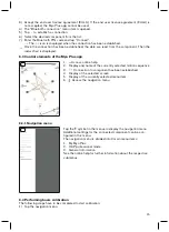
Страница 15: ...s app 6 1 Access online help 2 Display and name of the currently selected motion sequence 3 Connection to component has been established 4 Display of the selected screen 5 Display of the currently sel...

Страница 16: ...is 9 Use All electrode signals are displayed in the Myo Plus app via the Myo Plus TR The product is set up and configured via the Myo Plus app All information on use is found in the menu texts of the...

Страница 17: ...for medical devices This product meets the requirements of the 2014 53 EU directive The product meets the requirements of the RoHS Directive 2011 65 EU on the restriction of the use of certain hazardo...

Страница 18: ...d 2 this device must accept any interference including interference that may cause undesired operation of this device L utilisation de ce dispositif est autoris e seulement aux conditions suivantes 1...

Страница 19: ...voltage 6 V 11 1 V DC Current draw Max 25 mA Power supply 757B35 3 5 MyoEnergy Integral or 757B20 757B21 Energy Pack Lifetime 5 years Operating time MyoBock hand approx 14 hours bebionic hand approx 8...

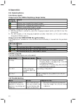
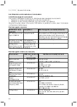
Страница 20: ...indicat or Event Charge level above 50 illuminated in green and Charge level below 50 flashing alternating green and orange Charge level below 5 illuminated in orange 13 1 2 Beep signals The followin...

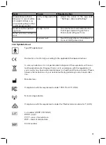
Страница 21: ...3 Symbols Used Type BF applied part Declaration of conformity according to the applicable European directives In some jurisdictions it is not permissible to dispose of these products with unsor ted ho...

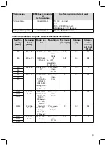
Страница 22: ...devices is unlikely Harmonics according to IEC 61000 3 2 Not applicable power below 75 W Voltage fluctu ations flicker accord ing to IEC 61000 3 3 Product meets the requirements of the standard Electr...

Страница 23: ...0 to 390 TETRA 400 Pulse modu lation 18 Hz 1 8 0 3 27 450 430 to 470 GMRS 460 FRS 460 FM 5 kHz deviation 1 kHz sine 1 8 0 3 28 710 745 780 704 to 787 LTE band 13 17 Pulse modu lation 217 Hz 0 2 0 3 9...

Страница 24: ...203 Otto Bock Healthcare Products GmbH Brehmstra e 16 1110 Wien Austria T 43 1 523 37 86 F 43 1 523 22 64 info austria ottobock com www ottobock com The product is covered by the following patents Pat...

Отзывы: