background image

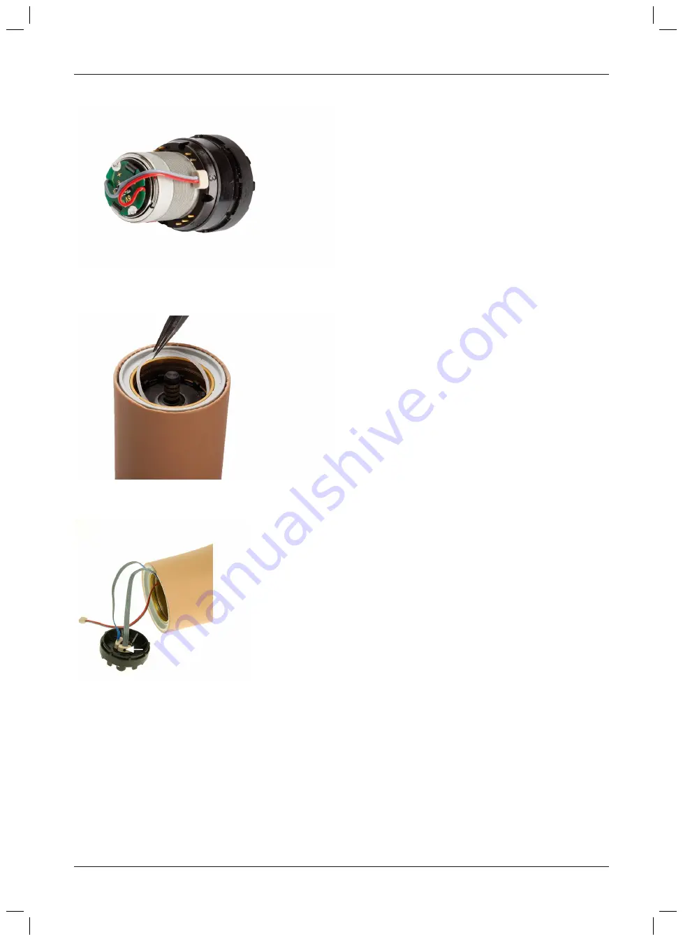
6.11 Wiring the product with the electric wrist rotator

1)  The  MyoRotronic  cannot  be  combined  with  the

elbow  joint.  The  MyoRotronic  would  be  destroyed
when operating the elbow joint.

2)  There  are  numbers  for  the  plug  contacts  on  the

plastic  housing  of  the  electric  wrist  rotator.  These
numbers  serve  as  orientation  for  connecting  the
cables.

3)  Attach the motor cable to one of the two contacts.

Connect two-pole receptacle to contact no. 3.

4)  Connect  three-pole  receptacle  to  contact  no.  2.

One  of  the  three-pole  connectors  is  marked  with  a
coloured dot.

5)  If  the  two  three-pole  connectors  are  interchanged

when connecting them to the two contacts, no func­
tion of the System Electric Hand or System Electric
Greifer is possible.

6)  To secure the coaxial plug, insert the retaining ring

into  the  groove  of  the  lamination  ring  using  tweez­
ers.

7)  Then  install  the  electric  wrist  rotator  in  the  lamina­

tion ring.

6.12 Wiring without electric wrist rotator

1)  One  of  the  two  three-pole  connectors  is  marked

with  a  coloured  dot  (arrow).  The  two  receptacles
must not be interchanged!

INFORMATION: The two-pole motor cable must
not be attached to the coaxial plug.

19

DynamicArm 12K100N

Preparation for use

Содержание DynamicArm 12K100N

Страница 1: ...DynamicArm 12K100N Instructions for use qualified personnel 3...

Страница 2: ...PT INFORMA O Adicionalmente ao manual de utiliza o impresso encontra se inclu do um CD com mais idiomas consultar a contracapa A pedido poss vel encomendar gratuitamente um exemplar impresso do manual...

Страница 3: ...ally controlled elbow joint driven by an electric motor It helps the wearer perform everyday tasks in combination with other prosthetic components see Page 5 A Li Ion battery integrated into the produ...

Страница 4: ...shes the electrical connection between the product electric wrist rotator and System Electric Hand or System Electric Greifer On delivery the forearm cable is rolled up in the forearm of the elbow joi...

Страница 5: ...anatomical replacement for the elbow joint and forearm 3 2 Conditions of use The product is suitable for patients with unilateral or bilateral upper arm amputations The product is intended exclusively...

Страница 6: ...WARNING Use of the product while operating a vehicle or machinery Risk of accident due to unexpected behaviour of the product Risk of injury due to faulty control or malfunction of the product Applica...

Страница 7: ...Improper use Injury due to loss of product functionality Instruct the patient in the proper use of the product CAUTION Manual unlocking of elbow lock under load Injury by release of elbow lock under...

Страница 8: ...erminal device before use so that a slight turn cannot disconnect the terminal device from the prosthesis CAUTION Incorrect donning and doffing of the product Injuries The product should always be fle...

Страница 9: ...152 instructions for use qualified per sonnel 1 pc 646D229 instructions for use user 1 pc 646T333 instructions for use qualified per sonnel 1 pc 646D644 service pass Accessories 1 pc strap clamp for U...

Страница 10: ...esis should be approx 1 cm shorter than the sound arm 2 Cut the forearm using a vibrating saw 3 Sand all sides of the cut edge at a right angle Smooth inner and outer sanded edges Round the inside edg...

Страница 11: ...efully and proceed exactly in the order described INFORMATION Read the relevant material safety data sheets before processing the 636K18 Orthocryl sealing resin compact adhesive and the 617H14 hardene...

Страница 12: ...m length For forearm lengths from 225 mm to 213 mm with 10S17 electric wrist rotator Make sure the 10S17 electric wrist rotator dummy is pushed over the cable protector cap This ensures correct axial...

Страница 13: ...et head screw 3 Or pull out the lamination ring cover on its own 4 Remove the cable protector cap using the hook 5 The cables are rolled up inside the cable protector cap When removing the cable prote...

Страница 14: ...electric wrist rotator Proceed as described above to cut to length and glue in the lamination ring INFORMATION If the foam disc has been glued into place the cables can be pulled out carefully throug...

Страница 15: ...de housing with the connected cables into the greased lamination ring It has to engage completely 2 The circuit board and the edge of the lamination ring must be parallel to each other 3 The electrode...

Страница 16: ...socket Make sure the friction adjustment screw and lamin ation ring thread recess are applied opposite to each other 3 Set the AFB dial to minimum compensation force 4 Extend the elbow and lock it wit...

Страница 17: ...into neutral position no outward or inward rotation 2 Affix the cable guide to the socket with cap screws centred in relation to the strap clamp and approx 30 mm away from the lamination ring CAUTION...

Страница 18: ...er arm section of the prosthesis while testing the joint function 4 Position 1 Low compensation that allows natural free swing of the arm while walking Position 2 Compensation increases progressively...

Страница 19: ...the three pole connectors is marked with a coloured dot 5 If the two three pole connectors are interchanged when connecting them to the two contacts no func tion of the System Electric Hand or System...

Страница 20: ...requency range of 50 60 Hz INFORMATION Please note the corresponding instructions for use of the battery charger 7 1 1 Charging process WARNING Charging the prosthesis without taking it off Risk of el...

Страница 21: ...arging the battery We recommend charging the product once a day when used by the patient on a daily basis The battery should be charged for at least 3 hours prior to initial use Note the permissible t...

Страница 22: ...s Risk of injury due to sudden flexion of the prosthesis Switch off the prosthesis before donning or doffing The prosthesis must always be flexed for donning and doffing 7 4 Switching modes 7 4 1 Swit...

Страница 23: ...stem Electric Gre ifer Control Two electrodes and 4 stage control element Indication For patients with two strong muscle signals Control type Proportional Switching between the components takes place...

Страница 24: ...with co contraction Switching to the hand Switching to the elbow joint Switching back Automatically switching back to the hand component takes place five seconds after relaxing the muscles DynamicArm...

Страница 25: ...s controlled by the linear control element Switching to the elbow joint Flexion Pull on the linear control element Extension Release of the linear control element 8 Cleaning and Care 1 Clean the produ...

Страница 26: ...mation that applies exclusively to specific countries is written in the official language of the respective country of use in this chapter This device complies with part 15 of the FCC Rules Operation...

Страница 27: ...ngton Ontario Canada Phone 1 800 665 3327 Caution Federal law USA restricts this device to sale by or on the order of a practitioner licensed by law of the State in which he she practices to use or or...

Страница 28: ...Disposal that is not in accordance with the regulations of your country may have a detri mental impact on health and the environment Please observe the instructions of your national authority pertain...

Страница 29: ...is present Function is present Very high high low very low Decreasing bat tery charge level No function Function is present Function is present 6 x low Battery charger was connected during opera tion...

Страница 30: ...30 DynamicArm 12K100N...

Страница 31: ...31 DynamicArm 12K100N...

Страница 32: ...ersion SB_2016 10 21 FM483 SB_210x297 Otto Bock Healthcare Products GmbH Brehmstra e 16 1110 Wien Austria T 43 1 523 37 86 F 43 1 523 22 64 info austria ottobock com www ottobock com Ottobock 647G152...

Отзывы: