background image

22

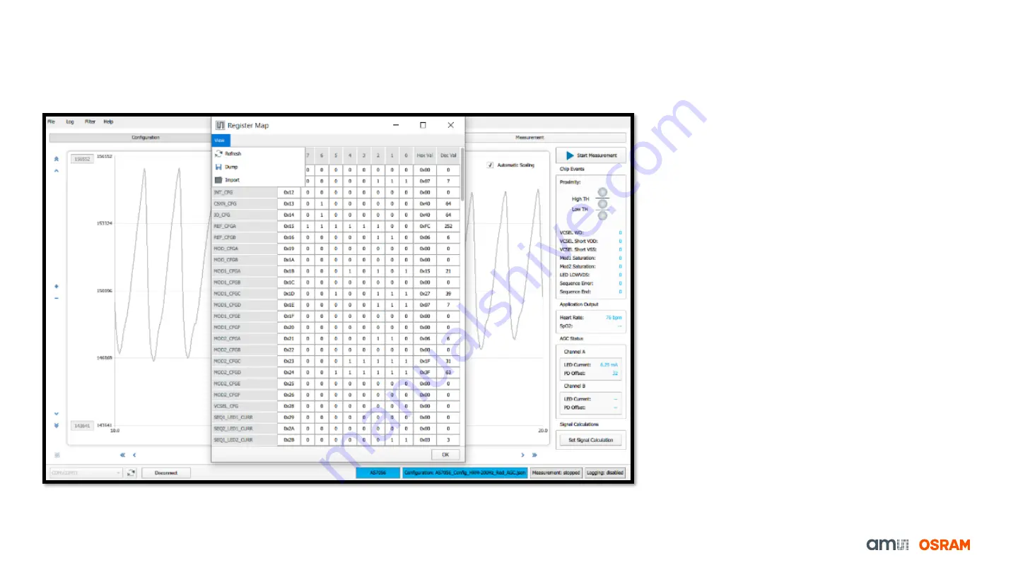
AS7056/57 Register Map

Register Map Configuration

• To check the current register Map, click on the tab

File

Register Map

(Fig. 21)

In the Register Map window,

o

The register values can be updated.

o

New register values can be entered.

o

New register values can be saved with a
name. Choose the file location, and then
click save.

Fig. 21: Register Map

Содержание AS7056

Страница 1: ...1 Sensing is life AS7056 57 Evaluation Kit 08 02 2022 Quick Start Guide...

Страница 2: ...2 AS7056 57 Evaluation Kit Quick Start Guide AS7056 57 EVK Install Software How to Use AS7056 57 PC Software Logging Data FW Upgrade...

Страница 3: ...ensor board 4 AS7057 Sensor board 5 Optical Barrier Cover Glass 6 Optical Barrier Cover Glass 7 Micro USB cable included in the box Fig 1 AS705x Evaluation Kit out of the box 1 2 3 4 5 6 SFH2201 SFH70...

Страница 4: ...ey 1 AS7056 AFE 2 Optical Module 3 VCSEL laser diode 4 AS7056 Sensor board with Optical Module 5 AS705x EVK Mainboard 6 BLE Controller Board 7 EVK power supply On Off button 8 Power Supply Test Interf...

Страница 5: ...ller executable and follow the instructions as shown in Fig 4 below left to right Fig 4 AS7056 57 Software Installation steps Note The EVK software is available for download please contact the ams OSR...

Страница 6: ...d 3 The green LED on the Bluetooth Microcontroller module and USB connector board will light up as soon as the board is powered 4 The green LED H1 on the mainboard will light up as soon as the board i...

Страница 7: ...list option load and save configuration file save the log file with the timestamp enable moving average filter if needed and update the firmware The one is the middle has control functions with three...

Страница 8: ...the user know which measurements could be done using these 3 Block diagram of the AS7056 57 Blue color shows which sub blocks are is enabled and grey color shows which sub blocks are disabled in a par...

Страница 9: ...nformation about the setting configurations which can be found in the Overview tab 2 Which parameter value is set for a specific measurement configuration can be seen in each parameter block For examp...

Страница 10: ...PD offset and LED current and algorithms like HRM and SpO2 The parameters related to HRM SpO2 applications can be individually reviewed and adjusted on this tab by enabling or disabling the Accelerom...

Страница 11: ...serve the Chip Events Application Output AGC Status 2 Start Measurement button 3 Proximity VCSEL MOD1 2 Sequence runtime conditions can be observed 4 Heart Rate SpO2 values will be displayed 5 AGC sta...

Страница 12: ...surface Rest forearms and hands on the table and let the finger tips rest Keep a light touch on the optical adapter no need to squeeze or press down too firmly Abrupt movement vibration during measure...

Страница 13: ...th module will start to blink as soon as the board connects with the GUI 6 After connecting Select the right configuration file from the provided configuration presets AS7057 HRM 200 Hz on finger usin...

Страница 14: ...module will start to blink as soon as the board connects with the GUI 6 After connecting Select the right configuration file from the provided configuration presets AS7057 SpO2 200 Hz on finger using...

Страница 15: ...as the board connects with the GUI 6 After connecting Select the right configuration file from the provided configuration presets AS7056 PPG 100 Hz Proximity 10 Hz for PPG signal using sequencer 1 wit...

Страница 16: ...to blink as soon as the board connects with the GUI 6 After connecting Select the right configuration file from the provided configuration presets AS7056 57 PPG 100Hz with MOD1 SUB1 3 for 3 channel P...

Страница 17: ...nning of the measurement in order to use the AAOC function 1 After connecting Select the right configuration file from the provided configuration presets AS7057 PPG Green AAOC to use the AAOC feature...

Страница 18: ...available ADC and DAC FSRs The number of subsamples used for calibration should be higher than 10 and in this example 50 samples are used for each calibration step The sampling frequency is set to 100...

Страница 19: ...calibration process starts and the progress is displayed in the status bar Depending on the settings used the calibration can only take a few seconds The result of the calibration is a table of 15 va...

Страница 20: ...ration table opens the copy dialog and the calibration table for DAC can be copied into the Modulator 1 Sequence 1 text field To enable AAOC signal reconstruction the Advanced AOC checkbox must be che...

Страница 21: ...y The display area can plot a maximum of three plots By default the plot area displays all the signals into one plot Left clicking on the channel name in the legend opens a dialog window to display th...

Страница 22: ...rent register Map click on the tab File Register Map Fig 21 In the Register Map window oThe register values can be updated oNew register values can be entered oNew register values can be saved with a...

Страница 23: ...log box Select the json configuration file you want to load and click Open To save the current configuration settings click on the tab File Save Configuration Fig 23 This will open the Save Configurat...

Страница 24: ...e data is saved in csv format Optionally the logging with timestamp can be selected This enables the saving to subsequent measurements results automatically with file names that has timestamp in it If...

Страница 25: ...2 Click on the tab Help Firmware Update to navigate to the dfu file latest firmware file 3 During the update process the green LED on the Bluetooth module will turn to red 4 After a successful update...

Страница 26: ...Sensing is life...

Отзывы: