background image

Section 3 - Controls and Indicators

3-6

31200205

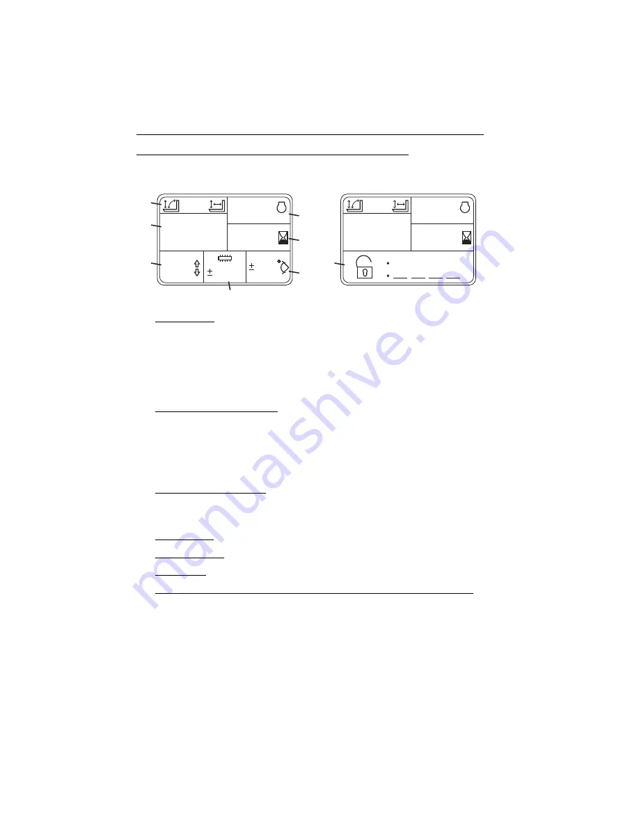
Display Screen

1.

Joystick Mode: Displays current joystick mode. Joystick mode can be changed 
by the machine owner in Operator Tools Menu (level 2 password required). See 
Service Manual for information.

a. Loader Joystick Pattern - Displays loader joystick pattern icon on left when

active. See page 3-20.

b. Lift Joystick Pattern - Displays lift joystick pattern icon on right when active.

See page 3-18.

2.

Speed and Power to Platform:

c. Speed (if equipped) - Telehandler travel speed displayed in kilometers per

hour (km/h) or miles per hour (m/h).

d. Transfer Power to Platform (if equipped for platform) - Assists with

transferring power to platform. Refer to the Platform for 3513PS, 4013PS,
4017PS Operation & Safety Manual.

3.

Driving Direction and Gear: Displays current driving condition.

a. Direction - Forward (F), Neutral (N) or Reverse (R).

b. Gear - First (1), Second (2), Third (3) or Fourth (4).

4.

Engine Speed: Displays engine speed in revolutions per minute (rpm).

5.

Operating Hours: Displays total hours of telehandler operation.

6.

Boom Angle: Displays boom angle in degrees. 0 degrees indicates horizontal.

7.

Continuous Auxiliary Hydraulics, Steering Mode Change and Platform Status:

a. Continuous Auxiliary Hydraulics - Displays flow value (-100% to +100%)

when continuous auxiliary hydraulics is activated. See Section
5 - Attachments and Hitches for 
details.

b. Steering Mode Change - Assists with steering mode change. See 

“Steer

Modes”

 on page 3-26 for details.

c. Platform Status (if equipped for platform) - Displays status when platform is

installed.

O

A

H

1

2

7

0

8

2

3

4

5

6

7

00

0000

0000

00

F2

RPM

km/h

100

0

00

0000

0000

RPM

km/h

1

DISPLAY SHOWN WITH CONTINUOUS 

AUXILIARY HYDRAULICS ACTIVE

DISPLAY SHOWN WITH ANTI THEFT 

ACTIVE AT SYSTEM START

Содержание JLG 3508PS

Страница 1: ...Safety Manual Original Instructions Keep this manual with machine at all times An Oshkosh Corporation Company Models 3508PS 3509PS 3512PS 3513PS 4008PS 4009PS 4012PS 4013PS 4017PS 31200205 Revised Mar...

Страница 2: ......

Страница 3: ...4 thru 4 9 5 4 5 6 5 15 9 3 November 16 2009 E Revised covers and page 9 7 February 26 2010 F Revised pages d 1 2 thru 1 6 1 9 2 1 2 4 thru 2 9 3 2 thru 3 8 3 11 3 12 3 14 thru 3 27 3 29 4 1 thru 4 1...

Страница 4: ...alified operator Operation within the U S A requires training per OSHA 1910 178 Operators of this equipment must possess a valid applicable driver s license be in good physical and mental condition ha...

Страница 5: ...in all instances where JLG products have been involved in an accident involving bodily injury or death of personnel or when damage has occurred to personal property or the JLG product FOR Accident Re...

Страница 6: ...ual if equipped Contact JLG Platform for 3513PS 4013PS 4017PS Operation Safety Manual if equipped for platform Contact JLG Note The following standards may be referenced in this manual ANSI is complia...

Страница 7: ...afety 1 2 Electrical Hazards 1 2 Tip Over Hazard 1 3 Travel Hazard 1 6 Load Falling Hazard 1 7 Lifting Personnel 1 8 Driving Hazards on Slopes 1 9 Pinch Points and Crush Hazards 1 10 Fall Hazard 1 12...

Страница 8: ...trol Lever 3 12 Load Stability Indicator LSI 3 14 Steering Column Adjuster 3 17 Joystick 3 18 Armrest and Right Hand Console 3 22 Accessory Control Lever 3 24 3 3 Anti Theft 3 25 3 4 Steer Modes 3 26...

Страница 9: ...ely 4 4 Picking Up a Load 4 4 Transporting a Load 4 5 Leveling Procedure 4 5 Placing a Load 4 6 Disengaging a Load 4 6 4 3 Operating with a Suspended Load 4 7 Lift Load Safely 4 7 Picking Up a Suspend...

Страница 10: ...3 JLG Quick Attach 5 13 Manitou Quick Attach 5 18 Hydraulic Operated Attachment 5 20 Platform Attachment If Equipped 5 20 5 7 Adjusting Moving Forks 5 21 5 8 Attachment Operation 5 22 Carriage w Forks...

Страница 11: ...chedules 7 3 8 1st 50 Hour Maintenance Schedule 7 3 50 250 500 Hour Maintenance Schedule 7 4 1000 1500 Hour Maintenance Schedule 7 5 7 4 Lubrication Schedules 7 6 8 Hour Lubrication Schedule 7 6 50 Ho...

Страница 12: ...ion 9 Specifications 9 1 Product Specifications 9 1 Fluid and Lubrication Capacities 9 1 Tires 9 2 Performance 9 3 Dimensions 9 6 Declaration of Vibration CE 9 8 Noise Emission Level CE 9 8 Index Insp...

Страница 13: ...dicates a potentially hazardous situation which if not avoided could result in death or serious injury CAUTION indicates a potentiality hazardous situation which if not avoided may result in minor or...

Страница 14: ...ctrical current NEVER operate the telehandler in an area where overhead power lines overhead or underground cables or other power sources may exist without ensuring the appropriate power or utility co...

Страница 15: ...lehandler Understand how to properly use the capacity charts located in cab DO NOT exceed rated lift capacity Be sure that the ground conditions are able to support the machine DO NOT raise boom unles...

Страница 16: ...ications for proper fill ratio and pressure requirements for tires equipped with ballast Always wear the seat belt Keep head arms hands legs and all other body parts inside operator s cab at all times...

Страница 17: ...swing and cause dangerous side loads even with tag lines DO NOT attempt to use telehandler frame leveling to compensate for load swing Keep heavy part of load closest to attachment Never drag the loa...

Страница 18: ...out for and avoid other personnel machinery and vehicles in the area Use a spotter if you DO NOT have a clear view Before moving be sure of a clear path and sound horn When driving retract boom and k...

Страница 19: ...afety Practices 1 7 31200205 Load Falling Hazard Never suspend load from forks or other parts of carriage DO NOT burn or drill holes in fork s Forks must be centered under load and spaced apart as far...

Страница 20: ...ices 1 8 31200205 Lifting Personnel When lifting personnel USE ONLY a JLG approved personnel work platform with proper capacity chart displayed in the cab DO NOT drive machine from cab when personnel...

Страница 21: ...For additional travel requirements refer to the appropriate capacity chart To avoid overspeeding the engine and drivetrain when driving down slopes downshift to a lower gear and use the service brake...

Страница 22: ...inch Points and Crush Hazards Stay clear of pinch points and rotating parts on the telehandler Stay clear of moving parts while engine is running Keep clear of steering tires and frame or other object...

Страница 23: ...fety Practices 1 11 31200205 Keep clear of boom holes Keep arms and hands clear of attachment tilt cylinder Keep hands and fingers clear of carriage and forks Keep others away while operating OW0240 O...

Страница 24: ...maintain 3 point contact when mounting or dismounting Never grab control levers or steering wheel when mounting or dismounting the machine DO NOT get off the machine until the shutdown procedure on pa...

Страница 25: ...Flammable Fuel DO NOT fill the fuel tank or service the fuel system near an open flame sparks or smoking materials Engine fuel is flammable and can cause a fire and or explosion Hydraulic Fluid DO NOT...

Страница 26: ...Section 1 General Safety Practices 1 14 31200205 This Page Intentionally Left Blank...

Страница 27: ...ion and Safety Manuals Operation Safety Manual located in cab manual holder 5 Walk Around Inspection See page 2 6 for details 6 Fluid Levels Check fluids including fuel brake fluid hydraulic oil engin...

Страница 28: ...see page 2 8 of all systems in an area free of overhead and ground level obstructions See Section 3 Controls and Indicators for more specific operating instructions WARNING If telehandler does not op...

Страница 29: ...lace as required OZ2122 8006612 8009815 1001094858 8 9 12 13M 8h 2 x 50h 1001094858A OPTIONAL 2999964 40 8009377 35 2603207 20 8009890 22 8009885 12 35 3700015 50h 1001094925A 2X 8h 8h 1001094925 17M...

Страница 30: ...2999964 40 8009377 35 2603207 20 8009890 22 8009885 12 35 8008657 8005616 8008657 1001094708 1001094708B 3700016 A 1706753 B 1706754 C 1706755 D 1706756 12 13 17M E 1706757 12 13 17M F 1706758 12 13 1...

Страница 31: ...A F27 15 A F29 15 A F30 15 A 1001094778A R L R L L R D 1001094778 1001094900 LIFT PATTERN 1001094900B 1001094901 LOADER PATTERN 1001094901B 1001094902 12 13 17M 1001094902B 1001094713 1001094713A 1001...

Страница 32: ...s excessive corrosion and other damage 1 Boom Sections and Lift Tilt Extend Retract Compensating Slave Cylinders Check front top side and rear wear pads for presence of grease Pivot pins secure hydrau...

Страница 33: ...her discrepancies 14 Boom Sensor 8 9 12 13M S N 1160005993 After including 1160005949 1160005950 17M S N 1160005937 After excluding 1160005952 1160005960 1160005963 1160005966 1160005978 See inspectio...

Страница 34: ...tional check 1 Service brake and parking brake operation 2 Forward and reverse travel 3 Each gear 4 Steering in both directions with engine at low idle steering lock to lock will not be reached Check...

Страница 35: ...OPS cab WARNING CRUSH HAZARD Never operate telehandler unless the overhead guard and cab structure are in good condition Any modification to this machine must be approved by JLG to assure compliance w...

Страница 36: ...t be closed during operation During operation the cab door window 2 must either be latched open or closed Open the cab door window and secure it in the latch Press the release button 3 inside the cab...

Страница 37: ...NDICATORS 3 1 GENERAL This section provides the necessary information needed to understand control functions Note The manufacturer has no direct control over machine application and operation The user...

Страница 38: ...raulic Quick Attach Switch if equipped Used in conjuction with the joystick to hydraulically lock or unlock an attachment 6 Power Emergency Stop Switch if equipped for platform Push down to shut off p...

Страница 39: ...ring modes are available See Steer Modes on page 3 26 12 Instrument Panel See page 3 4 13 Accessory Control Lever See page 3 24 14 LSI Indicator See page 3 14 15 Keypad See page 3 8 16 Joystick See pa...

Страница 40: ...ous auxiliary hydraulics are active 9 Trailer Turn Signal Indicator Illuminates when trailer turn signal is activated 10 Clutch Lock Indicator Illuminates when clutch lock feature is engaged 11 High B...

Страница 41: ...Charge Indicator Illuminates when battery is at low charge or charging system is not functioning properly 22 Transmission Oil Temperature Indicator Illuminates and buzzer sounds when transmission oil...

Страница 42: ...on and Gear Displays current driving condition a Direction Forward F Neutral N or Reverse R b Gear First 1 Second 2 Third 3 or Fourth 4 4 Engine Speed Displays engine speed in revolutions per minute r...

Страница 43: ...required to modify additional items Machine Speed Select units km h or m h to be displayed Engine Temperature Select units Celsius or Fahrenheit to be displayed Steering Alignment Mode Select mode man...

Страница 44: ...age 3 26 Note If machine is shut down during steer mode change it must be completed at restart 5 LSI Override Momentarily disables the automatic function cut out LED flashes while activated Depress an...

Страница 45: ...Section 3 Controls and Indicators 3 9 31200205 This Page Intentionally Left Blank...

Страница 46: ...eratures below 0 C 32 F Wait to start engine until preheat indicator on instrument panel goes out Position III Engine start In the event the engine does not start rotate key to position 0 then back to...

Страница 47: ...e brake stop telehandler in an appropriate parking area 2 Follow Shut Down Procedure on page 4 3 WARNING MACHINE ROLL AWAY HAZARD Always move park brake switch to ON position lower boom to ground and...

Страница 48: ...se the back up alarm will automatically sound Drive in reverse and turn only at slow rates of speed If clutch lock switch is activated see page 3 22 do not increase engine speed with the transmission...

Страница 49: ...nsmission control lever Twist hand grip to select gear Select the appropriate gear for the task being performed Use a lower gear when transporting a load Use a higher gear only when driving unloaded f...

Страница 50: ...first red LED illuminates As the telehandler reaches forward stability limitations and the second red LED illuminates the automatic function cut out is activated Certain functions are disabled i e boo...

Страница 51: ...ion cut out is activated All boom frame level and outrigger functions are disabled except for boom retract CE AUS and boom lift CE Retract boom to re enable functions In some instances the LSI system...

Страница 52: ...tices Test LSI 14 at the beginning of each work shift See Section 8 Additional Checks When placing a load ensure axles are not fully steered in either direction WARNING TIP OVER HAZARD If the green or...

Страница 53: ...ver 1 counterclockwise to unlock Place steering column in desired position Turn lever clockwise to lock WARNING TIP OVER CRUSH HAZARD Bring telehandler to a complete stop before shifting transmission...

Страница 54: ...unctions Move the joystick back to lift boom move joystick forward to lower boom move joystick right to extend boom move joystick left to retract boom The speed of boom functions depends upon the amou...

Страница 55: ...k to raise both outriggers Press and hold the button move the joystick left then forward to lower the left outrigger move the joystick left then back to raise the left outrigger Press and hold the but...

Страница 56: ...t boom move joystick forward to lower boom Extend retract is controlled by the roller switch 2 Push roller switch up to extend boom push roller switch down to retract boom The speed of boom functions...

Страница 57: ...gers Press and hold the button move the joystick left then forward to lower the left outrigger move the joystick left then back to raise the left outrigger Press and hold the button move the joystick...

Страница 58: ...switch to activate and keep transmission engaged while depressing service brake Depress back of switch to deactivate system and have transmission disengage while depressing service brake 5 Boom Work...

Страница 59: ...using the keypad up down arrow buttons see page 3 8 See Section 5 Attachments and Hitches for approved attachments and control instructions b Relieves auxiliary hydraulic circuit pressure See page 5 2...

Страница 60: ...ver must be manually returned to the center position to deactivate either turn signal The lever will not cancel automatically after a turn Pull lever up 4 to switch between low and high beam headlight...

Страница 61: ...buttons 2 to select the first digit 3 Depress OK button 3 to confirm and move to the next digit 4 Continue until the code is complete 5 If an incorrect code is entered the buzzer will sound briefly a...

Страница 62: ...ll change immediately after selection 1 Bring machine to a stop using service brake If front steer mode 2 is active and rear wheels are aligned go directly to step 4 2 With circle steer 1 or crab stee...

Страница 63: ...and display will show steering alignment screens until the change is complete After steering alignment is complete steer mode LED will illuminate solid 3 Turn the steering wheel until the rear wheels...

Страница 64: ...handle to adjust backrest angle 2 Fore Aft Use handle to move seat fore and aft 3 Suspension Use handle to adjust suspension to the appropriate weight setting 4 Weight Displays current weight setting...

Страница 65: ...ndle to move seat fore and aft 3 Suspension Use knob to adjust suspension to the appropriate weight setting 4 Height Use knob to adjust height to the appropriate setting 5 Lumbar Support Use knob to a...

Страница 66: ...ngled 2 With back straight in the seat couple the retractable end male end of the belt into the receptacle buckle end of the belt 3 With belt buckle positioned as low on the body as possible pull the...

Страница 67: ...e of the boom Use these indicators to determine boom extension when using the capacity chart see Use of the Capacity Chart on page 5 7 Boom Angle AUS The boom angle indicator 2 is located on the left...

Страница 68: ...Section 3 Controls and Indicators 3 32 31200205 This Page Intentionally Left Blank...

Страница 69: ...on switch to position III to engage starting motor Release key immediately when engine starts If engine fails to start within 20 seconds release key and allow starting motor to cool for a few minutes...

Страница 70: ...of booster battery Connect the negative jumper cable to negative post on booster battery Connect opposite end of negative jumper cable to ground point on machine away from discharged battery Follow s...

Страница 71: ...ng If the engine is not being used turn it off Shut Down Procedure When parking the telehandler park in a safe location on flat level ground and away from other equipment and or traffic lanes 1 Apply...

Страница 72: ...he conditions of the terrain Adjust travel speed and reduce amount of load if conditions warrant Avoid lifting double tiered loads Make sure load is clear of any adjacent obstacles Adjust spacing of f...

Страница 73: ...ake and move transmission control lever to NEUTRAL 3 Observe level indicator s to determine whether machine must be leveled prior to lifting load 4 Move boom attachment to 1 2 m 4 ft off ground AUS Mo...

Страница 74: ...then extend boom slowly until load is just above area where it is to be placed Lower the boom until the load rests in position and the forks are free to retract Disengaging a Load Once the load has be...

Страница 75: ...ad if conditions warrant Avoid lifting double tiered loads Make sure load is clear of any adjacent obstacles NEVER operate telehandler without a proper and legible capacity chart in the operator cab f...

Страница 76: ...could cause the telehandler to tip over The guide persons and operator must remain in constant communication verbal or hand and be in visual contact with the operator at all times Never place the guid...

Страница 77: ...lign load at the level load is to be placed then position boom slowly until load is just above area where it is to be placed Ensure that the guide persons and operator remain in constant communication...

Страница 78: ...roximately 30 40 cm 12 16 in above the ground 3 Fully tilt attachment back 4 Place protective shield over front bucket edge remove or reposition carriage forks toward the machine and secure to the car...

Страница 79: ...points as shown in the figure 5 Do not tiedown front of boom Note The user assumes all responsibility for choosing the proper method of transportation and tie down devices making sure the equipment u...

Страница 80: ...equipment to ensure the machine will be level when elevated The machine must remain level at all times while being lifted Ensure that the lifting device and equipment is adequately rated and suitable...

Страница 81: ...y of the above conditions are not met do not use the attachment The telehandler may not be equipped with the proper capacity chart or the attachment may not be approved for the model telehandler being...

Страница 82: ...100x1200 mm 1001107586 X Fork Extension 50x100 mm 1001112559 X X X X Fork Extension 60x100 mm 1001112560 X Bucket 0 51 m3 1001145722 X Bucket 0 9 m3 0930015 X X X X Bucket 1 0 m3 1001145724 X Bucket 1...

Страница 83: ...tension 50x100 mm 1001112559 X X X X X Fork Extension 60x100 mm 1001112560 X X X Bucket 0 51 m3 1001145722 X X X Bucket 0 9 m3 0930015 X X X X X Bucket 1 0 m3 1001145724 X X X Bucket 1 8 m3 0930016 X...

Страница 84: ...5 Attachments and Hitches 5 4 31200205 Platform 4 5 m 1001097355 X X X 1001112108 X X X 1001114462 X X X Attachment Part Number Applicable Standard Quick Attach 3513PS 4013PS 4017PS CE AUS CE AUS JLG...

Страница 85: ...Section 5 Attachments and Hitches 5 5 31200205 This Page Intentionally Left Blank...

Страница 86: ...center 3 Total attachment capacity is multiplied by the number of forks on the attachment if equipped up to the maximum capacity of the attachment Maximum capacity as indicated on the proper capacity...

Страница 87: ...the load is to be placed 5 On the capacity chart find the line for the height and follow it over to the distance 6 The number in the load zone where the two cross is the maximum capacity for this lift...

Страница 88: ...ng in good operating condition XXXXXXX EN 1459 B 1998 XXXX P N 1122334 P N 9988776 P N 1234567 P N 9876543 4 0 00 kg 3 5 00 kg 3 0 00 kg 2 5 00k g 2 0 00k g 1 5 00k g 1 0 00k g 500 kg 750 kg 400 kg 0...

Страница 89: ...identify the proper capacity chart on telehandlers equipped with outriggers refer to the following icons which may be located on the capacity chart Use when lifting a load with outriggers up Use when...

Страница 90: ...Y XX PSI X BAR 2 IN SERVICE WIND SPEED XXM S XXKM H 3 GROUND CONDITIONS FIRM SURFACES FOR LIFTING SLOPE AND LOAD LISTED ABOVE FOR BOTH CONFIGURATIONS 4 STANDARD USED AS 1418 19 2007 XXX MM LOAD CENTER...

Страница 91: ...identify the proper capacity chart on telehandlers equipped with outriggers refer to the following icons which may be located on the capacity chart Use when lifting a load with outriggers up Use when...

Страница 92: ...oad may be lifted Note This is a sample capacity chart only DO NOT use this chart use the one located in your operator cab Load Weight Distance Height OK to Lift 1 3 000 kg 6 614 lbs 3 m 9 8 ft 3 m 9...

Страница 93: ...mechanical quick attach 6 Quick Attach attachment tilt control in cab see page 3 18 for details WARNING CRUSH HAZARD Always be certain that carriage or attachment is properly positioned on boom and is...

Страница 94: ...ick attach forward to provide clearance Check to be sure lock pin is out 2 Align attachment pin with recess in attachment Raise boom slightly to engage attachment pin in recess 3 Tilt quick attach bac...

Страница 95: ...r cab to enable hydraulic quick attach function 2 Tilt quick attach forward to provide clearance Check to be sure lock pin is disengaged 3 Align attachment pin with recess in attachment Raise boom sli...

Страница 96: ...t protrude through the hole place the attachment on the ground and return to step 2 7 Turn auxiliary hydraulic valve handle 1 forward away from the operator cab to enable attachment auxiliary hydrauli...

Страница 97: ...ick attach back to engage attachment 4 Press and hold switch 2 and button 3 at the same time move joystick forward to engage lock pin or move joystick back to disengage lock pin 5 Raise boom to eye le...

Страница 98: ...chanical quick attach 6 Manitou Quick Attach attachment tilt control in cab see page 3 18 for details WARNING CRUSH HAZARD Always be certain that carriage or attachment is properly positioned on boom...

Страница 99: ...orward to provide clearance Check to be sure lock pin is out 2 Align attachment pin recess with attachment pin Raise boom slightly to engage attachment pin in recess 3 Tilt quick attach back to engage...

Страница 100: ...of auxiliary hydraulics switch three times must be accomplished within two seconds If buzzer sounds or continuous auxiliary hydraulics indicator illuminates repeat step 3 4 Perform Shut Down Procedure...

Страница 101: ...o Attachment Installation page 5 13 2 Elevate attachment to approximately 1 5 m 5 ft and tilt carriage forward until fork heel is free from attachment 3 Stand at the side of the carriage To slide fork...

Страница 102: ...described within this section reference the Lift joystick pattern Refer to page 3 20 if utilizing the Loader joystick pattern NOTICE EQUIPMENT DAMAGE Some attachments may contact the front tires or ma...

Страница 103: ...oller switch 2 controls carriage tilt Push roller switch down to tilt up Push roller switch up to tilt down Installation Procedure Refer to Attachment Installation on page 5 13 Equipment Damage Precau...

Страница 104: ...ge Capacity Chart To determine maximum capacity refer to on page 5 5 The joystick 1 controls movement of the boom The attachment tilt roller switch 2 controls carriage tilt Push roller switch down to...

Страница 105: ...back to shift forks left Installation Procedure Refer to Attachment Installation on page 5 13 Equipment Damage Precautions Do not use forks as a lever to pry material Excessive prying forces could da...

Страница 106: ...Carriage Load Chart To determine maximum capacity refer to on page 5 5 The joystick 1 controls movement of the boom The attachment tilt roller switch 2 controls carriage tilt Push roller switch down...

Страница 107: ...to shift forks in Installation Procedure Refer to Attachment Installation on page 5 13 Equipment Damage Precautions Do not use forks as a lever to pry material Excessive prying forces could damage fo...

Страница 108: ...per load rating and length The joystick 1 controls movement of the boom The attachment tilt roller switch 2 controls carriage tilt Push roller switch down to tilt up Push roller switch up to tilt down...

Страница 109: ...Equipment Damage Precautions The heavy part of the load must be against the carriage backrest Do not allow load center of gravity to be in front of tip of the supporting fork Do not pick up a load or...

Страница 110: ...1 controls movement of the boom The attachment tilt roller switch 2 controls fork mounted hook tilt Push roller switch down to tilt up Push roller switch up to tilt down Installation Procedure Ensure...

Страница 111: ...ing must be used Do not use with cubing or block forks Weight of rigging must be included as part of total load being lifted Do not use with mast carriage attachment Do not use fork mounted hook with...

Страница 112: ...ents set forth in Section 1 General Safety Practices The joystick 1 controls movement of the boom The attachment tilt roller switch 2 controls quick attach mounted hook tilt Push roller switch down to...

Страница 113: ...nts set forth in Section 1 General Safety Practices The joystick 1 controls movement of the boom The attachment tilt roller switch 2 controls truss boom tilt Push roller switch down to tilt up Push ro...

Страница 114: ...mine maximum capacity refer to on page 5 5 The joystick 1 controls movement of the boom The attachment tilt roller switch 2 controls bucket tilt Push roller switch down to tilt up Push roller switch u...

Страница 115: ...t down to dump load Equipment Damage Precautions Except for lifting or dumping a load the boom must be fully retracted for all bucket operations Do not corner load bucket Distribute material evenly wi...

Страница 116: ...iate Bucket Capacity Chart To determine maximum capacity refer to on page 5 5 The joystick 1 controls movement of the boom The attachment tilt roller switch 2 controls bucket tilt Push roller switch d...

Страница 117: ...enough to retain load and back away from pile Travel in accordance with requirements set forth in Section 1 General Safety Practices Open bucket or tilt bucket down to dump load Equipment Damage Prec...

Страница 118: ...e Bucket Capacity Chart To determine maximum capacity refer to on page 5 5 The joystick 1 controls movement of the boom The attachment tilt roller switch 2 controls bucket tilt Push roller switch down...

Страница 119: ...gh to retain load close grapple and back away from pile Travel in accordance with requirements set forth in Section 1 General Safety Practices Open grapple and tilt bucket down to dump load Equipment...

Страница 120: ...opriate Carriage Capacity Chart To determine maximum capacity refer to on page 5 5 The joystick 1 controls movement of the boom The attachment tilt roller switch 2 controls bucket tilt Push roller swi...

Страница 121: ...e parent forks and install the retaining pin behind the vertical shank of the fork Operation Close bucket gate level bucket and fully retract and lower boom to load material Distribute material evenly...

Страница 122: ...tilt Push roller switch down to tilt up Push roller switch up to tilt down Installation Procedure Refer to Attachment Installation on page 5 13 Operation from Cab The platform is to be only used on ma...

Страница 123: ...installed secure hitch to machine with hardware supplied with installation Pin Hitch CUNA C Italy Maximum combined weight of trailer and load 6000 kg 13 225 lb Maximum vertical weight at hitch interfa...

Страница 124: ...emove safety pin 1 and pull pin 2 from hitch 3 2 Align machine and tow eye of trailer 3 Place pin through hitch and tow eye Secure pin with safety pin 4 If equipped connect trailer harness to trailer...

Страница 125: ...afety pin 1 and pull pin 2 from hitch 3 2 Align machine and tow eye of trailer 3 Place pin through hitch and tow eye Secure pin with safety pin 4 If equipped connect trailer harness to trailer plug Ad...

Страница 126: ...and tow eye of trailer 3 Reverse machine toward trailer 4 After the tow eye contacts trigger 4 the pin and lever will be released 5 If equipped connect trailer harness to trailer plug Note Use lever...

Страница 127: ...e page 5 46 for Auto Hitch information Connecting trailer for towing 1 Raise Auto Hitch 1 to highest position 2 Remove safety pin 2 and lift locking latch 3 3 Insert safety pin to hold locking latch i...

Страница 128: ...3 off safety hooks 4 2 Pull safety hook release 5 3 Move joystick back to lower the hitch 6 to the required height 4 Reverse machine until the hitch is under the center of the tow eye 5 Move joystick...

Страница 129: ...ler towing applications The steering system permits manual steering if engine or power assist feature fails however steering will be slow and will require much greater force DO NOT attempt to tow a te...

Страница 130: ...n an individual basis Contact JLG Industries or the local Authorized Distributor for specific instructions Secure the telehandler using the following procedures 1 Clear the area around telehandler of...

Страница 131: ...s in position I 2 Depress back of auxiliary power switch 3 and hold in place to engage auxiliary power system 3 While holding the switch operate the boom joystick 4 until the attachment is at ground l...

Страница 132: ...ction 6 Emergency Procedures 6 4 31200205 6 4 CAB EMERGENCY EXIT In an emergency the rear window can be used to exit the telehandler Remove the latch pin 1 The window is then free to swing open OZ0240...

Страница 133: ...ral instructions that must be followed to keep this product in good operating condition The Operation Safety Manual and Service Manual contain more detailed service information with specific instructi...

Страница 134: ...light coating of engine oil to all linkage pivot points Intervals shown are for normal usage and conditions Adjust intervals for abnormal usage and conditions Drain engine and gear cases after operati...

Страница 135: ...Fuel Level Check Engine Oil Level Check Transmission Oil Level Check Hydraulic Oil Level Check Tire Condition Pressure Check Brake Fluid Level 8 EVERY Additional Checks Section 8 Check Wheel Lug Nut T...

Страница 136: ...vel Check Wheel End Oil Levels Air Filter Vacuator Valve Check Fan Belt Check Boom Chain Tension 17M Only Check Boom Wear Pads Check Transfer Case Oil Level Change Engine Oil and Filter Check LSI Cali...

Страница 137: ...1500 Hour Maintenance Schedule OZ1960 1500 EVERY Change Engine Coolant Change Hydraulic Fluid Filters Change Hydraulic Tank Breather Change Brake Fluid 1000 EVERY Change Axle Oil Change Wheel End Oil...

Страница 138: ...Section 7 Lubrication and Maintenance 7 6 31200205 7 4 LUBRICATION SCHEDULES 8 Hour Lubrication Schedule 8 9 12 13M EVERY 8 OZ2260...

Страница 139: ...Section 7 Lubrication and Maintenance 7 7 31200205 17M OZ2430 EVERY 8...

Страница 140: ...Section 7 Lubrication and Maintenance 7 8 31200205 50 Hour Lubrication Schedule 8 9 12 13M 2 x OZ2270 50 EVERY...

Страница 141: ...Section 7 Lubrication and Maintenance 7 9 31200205 17M OZ2440 2X 50 EVERY...

Страница 142: ...e on page 4 3 3 Open rear access door 2 4 Turn fuel tank cap 3 to remove from filler neck 4 5 Add diesel fuel as needed 6 Replace fuel tank cap 7 Close and secure rear access door Note Replenish diese...

Страница 143: ...Separator 1 Perform Shut Down Procedure on page 4 3 2 Open engine cover 3 Loosen drain cock 5 on underside of fuel filter 6 and allow all water to drain into a glass until clear fuel is visible Tighte...

Страница 144: ...Remove dust from bowl 4 Replace bowl and secure cover 5 Open engine cover 6 Locate air cleaner 4 and remove dust from vacuator valve 5 by squeezing bottom of valve to allow loose particles to fall ou...

Страница 145: ...be reused 3 Thoroughly clean the interior of the air cleaner canister and vacuator valve 4 Replace inner safety element 9 after every third primary element change If replacing the inner safety elemen...

Страница 146: ...crosshatched area of the dipstick 4 Replace dipstick 5 If oil is low remove oil fill cap 4 and add motor oil to bring oil up to the full mark in the crosshatch area 6 Replace oil fill cap 7 Close and...

Страница 147: ...form Shut Down Procedure on page 4 3 3 Check level of hydraulic oil at the sight gauge 5 on the hydraulic tank 6 The oil level should be visible in the gauge window 4 If hydraulic oil is low remove oi...

Страница 148: ...Wheel Replacement It is recommended that a replacement tire to be the same size ply and brand as originally installed Refer to the appropriate parts manual for ordering information If not using an ap...

Страница 149: ...ter each wheel installation Note If machine is equipped with directional tire assemblies the wheel and tire assemblies must be installed with the directional tread pattern arrows facing in the directi...

Страница 150: ...eck 1 Perform Shut Down Procedure on page 4 3 2 The brake fluid level 1 should be between the MIN and MAX marks on the reservoir 3 If brake fluid level is low add fluid as needed 2 Note All other work...

Страница 151: ...he ground 2 Check transmission oil level with engine at idle and oil at normal operating temperature 3 Open engine cover 4 Remove the transmission dipstick 3 and check oil level The oil level should b...

Страница 152: ...er 3 Check coolant level in overflow bottle 1 When coolant is hot bottle should be 1 2 to 3 4 full When coolant is cool bottle should be 1 4 to 1 2 full 4 If coolant is low remove overflow bottle cap...

Страница 153: ...Check 1 Perform Shut Down Procedure on page 4 3 2 Open engine cover 3 Wearing eye protection visually inspect the battery 3 Check terminals for corrosion Replace battery if it has a cracked melted or...

Страница 154: ...Level Check 1 Perform Shut Down Procedure on page 4 3 2 Open engine cover 3 The windshield washer fluid should be visible in the reservoir 1 4 If washer fluid level is low remove reservoir cap 2 and a...

Страница 155: ...963 1160005966 1160005978 1 Fully retract and level boom with no load Do not raise the boom during this test 2 Level frame using level in cab if equipped 3 Press the test button on the LSI display Thi...

Страница 156: ...able To check the system perform the following 1 Test system with machine on a level surface and no load 2 Shift transmission to neutral and engage park brake 3 Ensure outriggers and frame level funct...

Страница 157: ...vel are not operable To check the system perform the following 1 Test system with machine on a level surface and no load 2 Shift transmission to neutral and engage park brake 3 Ensure outriggers and f...

Страница 158: ...ck the system perform the following 1 Test system with machine on a level surface and no load 2 Shift transmission to neutral and engage park brake 3 Keep outriggers raised and level machine using lev...

Страница 159: ...and no load 2 Lower attachment to ground and shut off engine 3 Verify the power emergency stop switch is not depressed and the ignition switch is in position I 4 Depress back of auxiliary power switch...

Страница 160: ...Section 8 Additional Checks 8 6 31200205 This Page Intentionally Left Blank...

Страница 161: ...ulic System System Capacity 3508PS 4008PS 3509PS 4009PS 220 L 58 gal 3512PS 4012PS 3513PS 4013PS 4017PS 240 L 63 gal Reservoir Capacity to Full Mark 160 L 42 gal Auxiliary Hydraulic Circuit Max Flow 6...

Страница 162: ...Oil LSA SAE 90 Fuchs Titan Gear 85W 90 LS Castrol LSC SAE 90 Mobil Lube SHC LS 75W 90 Full Synthetic Mobil 1 SAE 75W 90 LS E P Air Conditioning System if equipped System Capacity 2 05 kg 4 5 lb Type...

Страница 163: ...me Level Not Equipped 500 kg 1102 lb 3509PS 3500 kg 7716 lb 4009PS 4000 kg 8818 lb 3512PS Frame Level Equipped Outriggers Engaged 3500 kg 7716 lb Outriggers Not Engaged 2500 kg 5512 lb Frame Level Not...

Страница 164: ...d Outriggers Engaged 1000 kg 2205 lb Outriggers Not Engaged 200 kg 441 lb Frame Level Not Equipped Outriggers Engaged 1000 kg 2205 lb Outriggers Not Engaged 150 kg 331 lb 4012PS Outriggers Engaged 140...

Страница 165: ...012PS 1 20 m 3 9 ft 3513PS 4013PS 1 85 m 6 1 ft 4017PS Outriggers Engaged 2 30 m 7 5 ft Outriggers Not Engaged 5 40 m 17 7 ft Maximum Travel Speed 3 spd 20 km h 12 4 mph 4 spd 35 km h 21 7 mph Towing...

Страница 166: ...00 mm 208 7 in 3509PS 4009PS 5620 mm 221 3 in 3512PS 4012PS 5790 mm 228 0 in 3513PS 4013PS 6000 mm 236 2 in 4017PS 6093 mm 239 9 in Ground Clearance 420 mm 16 5 in Turning Radius Over Tires 3800 mm 14...

Страница 167: ...level and fully retracted 3508PS 3850 kg 8487 lb 4008PS 4800 kg 10 582 lb 3509PS 3550 kg 7826 lb 4009PS 4500 kg 9920 lb 3512PS 4800 kg 10 582 lb 4012PS 5700 kg 12 566 lb 3513PS 5700 kg 12 566 lb 4013...

Страница 168: ...ft s 3509PS 0 8 m s 2 6 ft s 4009PS 0 7 m s 2 3 ft s 3512PS 0 8 m s 2 6 ft s 4012PS 0 8 m s 2 6 ft s 3513PS 0 8 m s 2 6 ft s 4013PS 0 7 m s 2 3 ft s 4017PS 0 7 m s 2 3 ft s Noise Emission Level CE The...

Страница 169: ...31 Extension 3 31 Boom Interlock Test 8 2 Brake Fluid Level 7 18 Brake System 9 1 Bucket 5 34 C Cab Emergency Exit 6 4 Capacities 9 1 Capacity 5 6 Capacity Chart Example 5 12 Sample AUS 5 10 Sample CE...

Страница 170: ...lic System 9 1 I Ignition 3 10 Instrument Panel 3 4 J Joystick Lift Pattern 3 18 Loader Pattern 3 20 K Keypad 3 8 L Leveling Procedure 4 5 4 8 Lifting Personnel 1 8 Load Falling Hazard 1 7 LSI 3 14 Te...

Страница 171: ...eat Belt 3 30 Service and Maintenance Schedule 1000 Hour 7 5 1500 Hour 7 5 1st 50 Hour 7 3 250 Hour 7 4 50 Hour 7 4 500 Hour 7 4 8 Hour 7 3 Shut Down Procedure 4 3 Side Shift Carriage 5 24 Specificati...

Страница 172: ...Index 4 31200205 V Vibration 9 8 W Walk Around Inspection 2 6 Warm Up Check 2 8 Wheel Installation 7 17 Wheel Lug Nut 9 2 Wheel Replacement 7 16 Windows 2 10 Windshield Washer Fluid Level 7 22...

Страница 173: ...Inspection Maintenance and Repair Log Serial Number ______________________________ Date Comments Inspection Maintenance and Repair Log...

Страница 174: ...Inspection Maintenance and Repair Log Date Comments...

Страница 175: ...rented units should not be included on this form Mfg Model _______________________________________________________________ Serial Number ____________________________________________________________ Pr...

Страница 176: ......

Страница 177: ......

Страница 178: ...rmany 49 0 421 69350 0 49 0 421 69350 45 Email german parts jlg com JLG Equipment Services Ltd Rm 1107 Landmark North 39 Lung Sum Avenue Sheung Shui N T Hong Kong 852 2639 5783 852 2639 5797 JLG Indus...

Отзывы: