Ormed ATRTOMOT-K1 Скачать руководство пользователя страница 2

1. History

2

2. Purpose

2

3. General

2

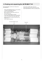
4. Packing and unpacking the ARTROMOT®-K1

5. Block diagram of the electronic

parts ARTROMOT®-K1

6. Bill of material for service parts ARTROMOT®-K1

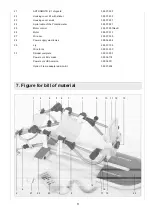
7. Figure for bill of material

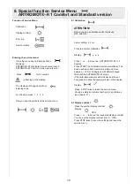
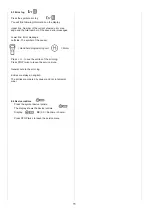
8. Special function Service menu for 
     ARTROMOT®-K1Comfort and Standard version

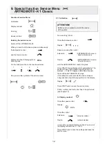
9. Special function Service menu for 
     ARTROMOT®-K1Classic

10. How to perform repairs

11. Checklist of safety and function test
      ARTROMOT®-K1Comfort and Standard version

12. Checklist of safety and function test
      ARTROMOT®-K1Classic  

5

6

7

8

10

12

14

15

16

2

The purpose of this Service Manual is to help you make
simple repairs on the ARTROMOT®-K1. Only authorized
staff may perform repairs and maintenance as the manufac-
turer’s warranty and liability would otherwise be invalidated.
Only original parts may be used for servicing in accordance
with the attached spare parts list.

3.1 Electronics, connection cables

1

2

3

4

No plugs may be connected or disconnected while the
unit is switched on. Always switch the ARTROMOT®-K1
off before connecting or disconnecting a plug.
The locks for spiral cable for the hand-held program-
ming unit have to be closed at all times.
When you assembling with electronic parts make sure
to use ESD (Electro Static Discharge) equipment.
Only original chip cards may be used. Insert the chip
cards so that ARTROMOT® is visible.
If you have to exchange any of the printed circuit boards
including the knee electronics, hand held programming
unit, motor control or power supply electronics you have
to perform a calibration.
Possible errors: Errors will be displayed on the hand-
held programming unit as follows shown:

Potentiometer error:

Wrong angle information

-> 

Check the femur settings

-> 

Replace knee electronics (Pos. 5)

-> 

Replace motor control (Pos. 25)

Failure at the potentiometer:

Connection to the potentiometer is interrupted

-> 

Replace the spiral cable of the potentiometer (Pos. 24)

-> 

Replace knee electronics (Pos. 5)

-> 

Replace motor control (Pos. 25)

Motor driver error:

The motor driver IC reported an error

-> 

Replace motor control (Pos. 25)

Motor error:

The motor did not turn properly

-> 

Replace motor control (Pos. 25)

-> 

Replace the motor (Pos. 26)

Table of contents

2. Purpose

1. History

Revision

Date

Name

Change

1

10.02.2006

S. Herr

Service Manual
created

2                14.07.2006          S. Herr

Pos. 25, 
chapter 10

3                14.08.2006          S.Herr

Pos. 20, 
Chapter 9, 12

3. General

ERROR

XX

(XX = Number of the error)

Содержание ATRTOMOT-K1

Страница 1: ...Service Manual ARTROMOT K1...

Страница 2: ...for the hand held program ming unit have to be closed at all times When you assembling with electronic parts make sure to use ESD Electro Static Discharge equipment Only original chip cards may be us...

Страница 3: ...ld programming unit Pos 20 3 21 Range exceeded The measured angle is out of the range of motion Replace motor control Pos 25 22 ROM error in the hand held programming unit Memory error in the hand hel...

Страница 4: ...held programming unit Use the correct hand held programming unit Pos 20 46 Handset error internal communication Invalid interchip communication inside the hand held programming unit Replace the hand h...

Страница 5: ...iginal packaging for transport Put the hand held programming unit into the specified cutout of the styrofoam and fix it with adhesive tape Set the femur lenght on maximum and the lower leg setting on...

Страница 6: ...ts ARTROMOT K1 Display Control logic Motor driver Micro processor Motor Control Hand held programming unit Microprocessor Control logic Pot Control Motor Pot Power supply 24 V DV Optional card reader...

Страница 7: ...10 Belt loop 2 0013 087 11 Footrest complete with plate clamping lever belt 2 0037 032 Footrest 2 0013 300 Footplate 2 0037 168 Oval plate 2 0013 298 12 Fixation screw GN534 40 M6sw Rubber puffer comp...

Страница 8: ...trol 2 0037 901RevB 26 Motor 0 0037 010 27 Wire set 2 0037 005 28 Power supply electronics 0 0034 244 29 Lip 2 0037 105 Wire for lip 0 0031 300 30 Spindel complete 0 0037 203 Power cord EU version 0 0...

Страница 9: ...9 27 26 24 25 29 28 Position 30...

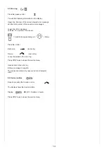
Страница 10: ...tion starts automatically The device will reach both maximum points and move between 10 bis 120 degrees with different speed Wait until the ARTROMOT K1 stops If the calibration was succesful the devic...

Страница 11: ...The symbol of the causer Hand held programming unit Motor Press or to see the entries of the error log Press STOP twice to leave the service menu General note to the error log Entries are always in en...

Страница 12: ...ion ARTROMOT K1 move in direction Extension Flexion ARTROMOT K1 move in direction Flexion until the ARTROMOT K1 reach 0 degrees Press START the calibration starts automatically The device will reach b...

Страница 13: ...and held programming unit Motor Press the control Extension last entry Flexion next entry to see the entries of the error log Press STOP twice to leave the service menu General note to the error log E...

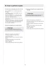
Страница 14: ...make sure to use ESD Electro Static Discharge equipment Remove the housing cover see chapter 10 1 Pull out the connectors of the motor control Loosen the four screws Exchange the defective motor cont...

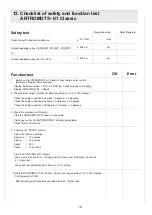
Страница 15: ...degrees Tolerance 5 degrees Check the angle in position 100 degrees Tolerance 5 degrees 3 Check the emergency off function Start the ARTROMOT K1 in any mode Press any key the ARTROMOT K1 will stop im...

Страница 16: ...ion 0 degrees Tolerance 5 degrees Check the angle in position 60 degrees Tolerance 5 degrees Check the angle in position 100 degrees Tolerance 5 degrees 3 Check the emergency off function Start the AR...

Страница 17: ...DIN EN 13485 ORMED Nr 018 829 01 ORMED GmbH Co KG Merzhauser Stra e 112 D 79100 Freiburg Tel 49 761 4566 01 Fax 49 0761 4566 5501 www ormed de E Mail info ormed de...

Отзывы: