SMTS II for GPC-XP Technical Guide
GPC-XP CONTROLLER SCREENS
13
Unit Selection and Analog Inputs
My System Unit Selection
From the
Main Screen
,
touch
the
< My System>
icon.
The
Selected Unit Screen
will appear. See
Figure 13
.
NOTE:
If you have chosen the
One to One Unit Connection
in the
System Manager Settings Screen
, this screen
(
Figure 13
) will not appear. Instead, the unit’s fi rst
Status Screen
will appear.
Back
Selected Unit [Loop 1 - Unit 1]
1
GO
0
1
0
-
-
-
-
+
+
+
+
Figure 13: Unit Selection Screen
In
Figure 13
, Loop 1 and Unit 1 are selected as indicated in the fi gure
with white text. They also appear in the
Top Menu Bar
in brackets.
Use the
<+>
and
<->
buttons to move up and down through the loops
and units.
Enter
the desired
Loop #
and
Unit #
and then
touch
<GO>
to access the unit’s
Status Screen
.
Viewing / Confi guring GPC-XP Status
Screens
Figures 14-27
depict the
GPC-XP
Status Screens
and corresponding
data entry screens
associated with them
. Notice that the controller
is identifi ed by loop number and unit number - in this case, 0001
represents Unit 1 with a stand-alone connection.
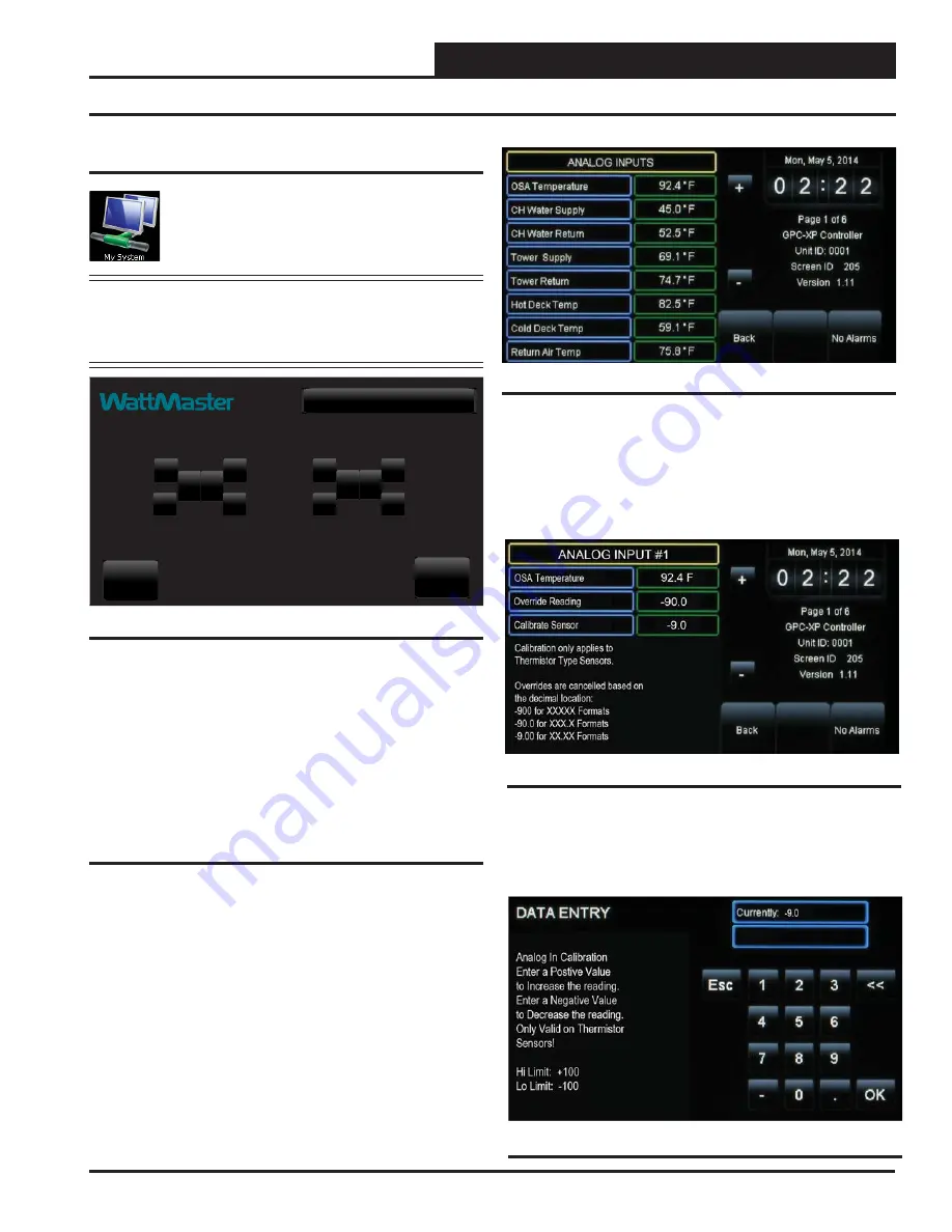
Figure 14: Analog Inputs Screen
While in each
Status Screen
,
touch
the
<+>
and
<->
buttons to view
more status screens. These screens roll back to the
fi rst
Status Screen
.
Figure 15: Analog Input Details Screen
Analog Inputs:
Thermistor sensors can be calibrated and all read-
ings can be overridden to specifi c values by Level 3 users. To do
this, while in the
Analog Input Screen
,
touch
the value fi eld for the
sensor you would like to calibrate or override.
In this example below (
Figure 15
), Analog Input #1 - OSA Tem-
perature Sensor is selected.
Calibrate Sensor:
To calibrate a thermistor sensor, touch the Cali-
brate Sensor value fi eld. The
Data Entry Screen
will appear.
Type
a
positive value to increase the reading or a negative value to decrease
the reading. High Limit: +100. Low Limit: -100. P
ress
<OK>
to save.
Figure 16: Calibrate Sensor Data Entry Screen


