background image

Zone

Zone


MAIN SCREEN FUNCTIONS

      SMTS II for GPC-XP Technical Guide

12

System Manager Settings

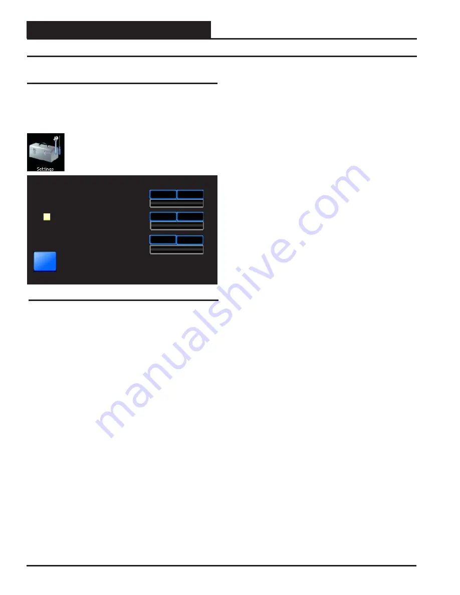
Figure 12:  System Manager Settings Screen

30

System Manager Settings

Backlight Timeout

Backlight Intensity

System Manager Address

Back

30

Minutes

30

50

%

30

63

One to One Unit Connection

System Manager Version:  1.02

  System Manager Settings

Additional system settings are available under the 

<Settings>


icon. These include setting the Backlight Timeout, the Backlight 
Intensity Percentage, the System Manager Address, and One to One 
Unit Connection.

From the 

Main Screen

touch 

the 

< Settings> 

icon. 

The  

System Manager Settings Screen 

will appear. See 

Figure 12

.

Backlight Timeout: 

 This setting is actually a setting for three 

separate functions—Backlight Timeout, 

Main Screen

 Timeout, and 

Passcode Timeout. To set the Backlight Timeout, e

nter

 the amount 

of time you wish the screen to maintain the active intensity level 
after the last touch pad activity occurs. The High limit is 30 and the 
Low limit is 0. 0 = No Timeout. The System Manager TS II will 
return to the 

Main Screen

 display at the same rate as the Backlight 

Timeout, except that if set to 0, the 

Main Screen

 will display after 2 

minutes. The Passcode will timeout at the same rate as the Backlight 
Timeout, except that if set to 0, the Passcode will timeout after 2 
minutes and will return to System Secured Setting.

 Backlight Intensity Percentage: 


Enter 

the percentage of light 

level you wish to maintain whenever touch pad activity occurs. The 
High limit is 100 and the Low limit is 0. 

 System Manager  Address: 


Enter

 the address of the System 

Manager TS II. 0 = Stand Alone Mode. 63 = Network System. 1-60 
= Multiple Managers based on the following defi nitions:

•  

Stand Alone

If your System Manager TS II is connected to 

one controller and you are not using a CommLink or MiniLink 
anywhere on the loop, your system is 

Stand Alone

. If your 

System Manager TS II is connected to more than one controller 
daisy-chained together and you are not using a CommLink or 
MiniLink anywhere on the loop, your system is 

Interconnected

If you have either a 

Stand Alone

 or 

Interconnected

 system, 

you must 

enter


<0>

 for 

Stand Alone Mode

. In order to view 

all controllers on an 

Interconnected System

, make sure that 

One to One Unit Connection, described below, is not selected.

•  

Network—

If you are using this System Manager TS II on a com-

munications loop that has a MiniLink or CommLink installed 
and you have a single System Manager TS II for your entire 
system, you must 

enter


<63>

 for 

Network System

.

•  

Multiple Managers—

If you are using this System Manager TS 

II on a communications loop, have a MiniLink or CommLink 
installed, and have more than one System Manager TS II, then 
you need to operate in 

Multiple Managers Mode

Enter

 the ad-

dress 

<1-60>

 at which you want this particular System Manager 

TS II to be set. When  more than one System Manager TS II 
is used on a local loop, each must be set with a unique address 
different from any other device on that loop. If you want one 
of the System Manager TS II’s to be able to indicate alarms for 
the entire system, you must 

ente

<63>

 for 

Network System


for that particular System Manager TS II. 


One to One Unit Connection:  

If your System Manager TS II 

is directly connected to the GPC-XP Controller, you may wish to 
select this option to bypass the 

Unit Selection Screen

 and go directly 

to the unit’s 

Status Screen

. The controller must be set to address #1 

for this to work. 

Touch

 the black box to the left of this item on the 

screen to select it. The box will turn white. If you wish to deselect 
this option, simply 

touch 

the box again.


System Manager Version:

  The version number of the System 

Manager software appears on the bottom menu bar. This version 
number is important to know for troubleshooting purposes.

Содержание OE392-10-GPCXP

Страница 1: ...System Manager TS II For GPC XP Technical Guide GPC XP Controller Code YS102432 Revision 4 0 and up ...

Страница 2: ...wing and Setting Holidays 17 Schedule Override 18 ALARMS 18 Viewing Enabling Disabling Alarms 18 APPENDIX 19 Troubleshooting System Manager TS II LEDs Buttons Dipswitches and Jumpers 19 Military Time Conversion 20 INDEX 21 WattMaster Controls Inc 8500 NW River Park Drive Parkville MO 64152 Toll Free Phone 866 918 1100 PH 816 505 1100 FAX 816 505 1101 E mail mail wattmaster com Visit our web site a...

Страница 3: ...amming Comes equipped with real time clock backup power supply for short power losses Provides icons to indicate alarm conditions LEDs behind plastic panel indicate power communica tions and operation Plastic enclosure allows for easy flush wall mounting in hollow drywall or surface mounting on solid wall surface System Manager TS II System Requirements The System Manager TS II is packaged and ass...

Страница 4: ...arily freeze the touch pad before you attempt to clean your screen See the Troubleshooting section on page 19 for details Wiring The System Manager TS II is connected to the local communications loop of the Orion system via 18AWG 2 conductor twisted pair with shield wire connected to the T SHLD R communication terminals on the back of the System Manager TS II The communications wire used can be ei...

Страница 5: ...SMTS II for GPC XP Technical Guide COMPONENTS WIRING 5 Flush Wall Mount Dimensions and Components Figure 3 System Manager TS II Dimensions and Components Flush Wall Mount ...

Страница 6: ...COMPONENTS WIRING SMTS II for GPC XP Technical Guide 6 Surface Mount Dimensions and Components Figure 4 System Manager TS II Dimensions and Components Surface Mount ...

Страница 7: ...niLink s Both Jumpers Must Be OFF OFF OPT4 OPT3 OPT2 OPT1 SW1 NOTE Dip Switch OPT1 Should Be Set To ON When GPC XP Is Set To High Speed OPT2 OPT3 As Of April 2014 OPT4 Should Be Set To ON By Default Previous Versions Should Be Set To OFF If You See Your Screen Is Not Centered Correctly Switch OPT4 To The Opposite Position Should Be Set To OFF COM FROM GND CUT TO ISOLATE WATTMASTER CONTROLS YS10243...

Страница 8: ...ion System settings are only accessible to a Level 3 user The Set Time Date icon takes you to the Set Time and Date Screen Any level of user can set the time and date Navigation Buttons See Table 2 for a list of Navigation buttons and their functions Button Function Back Use the Back button while in a Data Entry Screen to return to the Status Screen Use the Back button while in a Status Screen to ...

Страница 9: ...to the Touch Screen while the GPC XP is initializing This can cause programming errors Main Screen Once you have connected your System Manager TS II to a control ler and have powered it up with the proper power supply the Main Screen will appear See Figure 6 Figure 7 Login Screen Enter the 4 digit Passcode for the required Level Level 1 Can change space setpoints Level 2 Can change schedules Level...

Страница 10: ...en will appear See Figure 8 To change a passcode touch the blue highlighted box containing the current passcode The keypad will appear with instructions for changing the passcode See Figure 9 The current passcode will appear on the top menu bar Type in the new four digit passcode You cannot use the period or minus char acters in your passcode Use the key if you make a mistake Touch Esc to return t...

Страница 11: ...When you are finished setting the clock touch the Broadcast button to broadcast the Time and Date to all Units The following message will appear Figure 10 Set Time Date Screen Back Set Time Date Broadcast System Manager Settings Mon Tue Wed Hour Minute Month Day Year 14 12 1 16 14 Sun Thu Sun Thu Fri Sun Fri Sat Sun Sat Esc 1 2 3 4 7 0 9 8 5 6 OK Currently 10 DATA ENTRY Set Clock Hour Enter the Cu...

Страница 12: ...t using a CommLink or MiniLink anywhere on the loop your system is Stand Alone If your System Manager TS II is connected to more than one controller daisy chained together and you are not using a CommLink or MiniLink anywhere on the loop your system is Interconnected If you have either a Stand Alone or Interconnected system you must enter 0 for Stand Alone Mode In order to view all controllers on ...

Страница 13: ... Status Screens and corresponding data entry screens associated with them Notice that the controller is identified by loop number and unit number in this case 0001 represents Unit 1 with a stand alone connection Figure 14 Analog Inputs Screen While in each Status Screen touch the and buttons to view more status screens These screens roll back to the first Status Screen Figure 15 Analog Input Detai...

Страница 14: ... operation To do this while in the Relay Outputs Screen Figure 20 touch the value field for the Relay you would like to force on or off In the example below Figure 21 Relay Output 5 Tower Fan is selected Touch the Tower Fan s data field The Relay Output Force Mode Screen will appear Figure 22 Figure 21 Relay Output Details Screen Analog Inputs Binary Inputs and Relay Outputs Override Reading To ov...

Страница 15: ...e Relay Off Runtime Reset You can also touch the Runtime Hrs and Runtime Minutes data field to reset Runtimes Figure 21 Analog Outputs From the Analog Outputs Screen Figure 23 you can access the detail screen by selecting one of the data fields In the example below Figure 24 Tower Fan Speed is selected Force Analog Output From the Analog Output Detail Screen Figure 24 you can access the Force Scre...

Страница 16: ...be entered in military time format See the Military Time Table in the Appendix page 20 Touch OK to save the time you entered or touch Esc to exit the Schedule Times Screen without changing the time and return to the Week Schedules Screen Figure 29 To eliminate a schedule from any event simply enter a zero for the Start and Stop time for that day The screen will display 12 00 am for both the Start ...

Страница 17: ...he NORMAL button for the desired Schedule The Holidays Schedule Screen will appear starting with the current month and year See Figure 32 Figure 32 Holidays Schedule Screen Figure 31 Status Screen 6 Schedules The holidays in the screen will initially not be set You can only set holidays for the current year Simply touch the day s of the month to select holidays Touch the button to go back one mont...

Страница 18: ...sly Prism 2 does have to be running for emailing or texting alarms to occur To enable an alarm simply touch the gray square next to each alarm Awhite box designates that the alarm is enabled To disable the alarm simply touch the square again A gray box designates that the alarm category is disabled When an alarm is enabled and there is no alarm condition the word OK appears in a box next to the ty...

Страница 19: ...ols Technical Support you may have to perform diagnostics on your System Manager TS II Press this button to do so Touch Screen Suspend Button Press this button to temporarily freeze the touch screen function of your System Manager TS II in order to clean the screen Always use a dry dust free cloth to clean the screen OPT1 Dipswitch OPT1 Dipswitch should be ON if the GPC XP is set to High Speed Thi...

Страница 20: ...early identify the time of day Since military time uses a unique two digit number to identify each of the 24 hours in a day a m and p m are unnecessary The following table summarizes the relationship between regular and military time Regular Time Military Time 12 00 a m 0000 12 30 a m 0030 1 00 a m 0100 1 30 a m 0130 2 00 a m 0200 2 30 a m 0230 3 00 a m 0300 3 30 a m 0330 4 00 a m 0400 4 30 a m 04...

Страница 21: ...s 8 Icons 8 Diagnostics Button 19 Dimensions 5 Dipswitch Settings 4 Down Arrow Key Function 8 E Edit Passcodes 10 Environmental Requirements 4 Esc Key Function 8 F Features 3 Flush Wall Mount 4 5 Force Analog Output 15 Force Modes 17 G GPC XP Alarms Configuring 18 Enabling Disabling 18 GPC XP Controller Wiring to SMTS 7 GPC XP Controller Alarm Status Screen 18 H Holidays 17 Setting 17 Viewing 17 H...

Страница 22: ...ed 8 SEND TO All Days 16 SEND TO Weekdays 16 Sensor Override Data Entry Screen 14 SET 24 Hr Mode 16 Set Clock Hour 11 Set Time and Date 11 Set Time Date Icon Description 8 Set Time Date Screen 11 Settings Icon Description 8 Setting the System Clock 11 Stand Alone 12 Surface Mount 6 Suspend Button 4 19 System Manager Address 12 System Manager Passcode 9 System Manager Passcode Levels Screen 10 Syst...

Страница 23: ...SMTS II for GPC XP Technical Guide NOTES 23 ...

Страница 24: ...SMTSII GPCXP TGD 01A Printed in the USA May 2014 All rights reserved Copyright 2014 WattMaster Controls Inc 8500 NW River Park Drive Parkville MO 64152 Phone 866 918 1100 www orioncontrols com Fax 816 505 1101 ...

Отзывы: