


4
Note
•
When connecting, check the indication on the driver
front panel and properly connect according to the
polarity of the power supply. Reverse-polarity
connection may cause damage to the driver.
•
The power-supply circuit and the RS-485
communication circuit are not insulated. Therefore,
when controlling multiple drivers via RS-485
communication, the reverse polarity of the power
supply will cause a short circuit and may result in
damage to the drivers.
•
Use an accessory motor cable when extending the
wiring distance between the actuator and driver.
When installing the actuator to a moving part, use
an accessory flexible cable offering excellent
flexibility.
Power supply current capacity
Motor model
Power supply
input voltage
Power supply
current capacity
DG60
1.3 A or more
EAS4
1.8 A or more
EAS6
24 VDC±5%
3.8 A or more
CN1
1.
Strip the insulation cover of the lead wire by 7 mm (0.28 in.)
2.
Insert each lead wire into the CN1 connector and tighten the
screw using a screwdriver.
Tightening torque: 0.22 to 0.25 N·m (31 to 35 oz-in)
3.
Insert the CN1 connector into CN1 and tighten the screws.
Tightening torque: 0.4 N·m (56 oz-in)
7 mm
(0.28 in.)
Lead wire
CN1 connector
CN1
Tightening torque:
0.4 N·m (56 oz-in)
•
Pin assignment
Pin No.
Signal
name
Description
1 MB1
Electromagnetic brake
−
(Black)
2 MB2
Electromagnetic brake+
(White)
3
+
+24 VDC/48 VDC power
supply input
4
-
GND
5 FG
Frame
Ground
1
2
3
4
5
CN3
Connect to CN3
Cable for
OPX-2A
or
communication cable for
data setting software
Caution
The power supply connector (CN1), data edit
connector (CN3) and RS-485 communication
connectors (CN6/CN7) of the driver are not
electrically insulated. When grounding the
positive terminal of the power supply, do not
connect any equipment (PC, etc.) whose negative
terminal is grounded. Doing so may cause the
driver and these equipment to short, damaging
both.
CN5, CN8, CN9
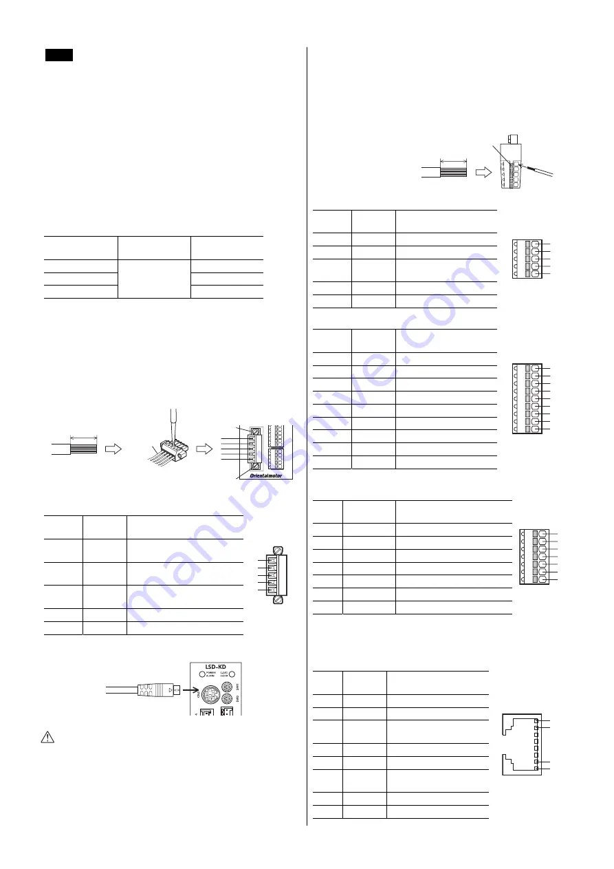
•
Connecting method
1.
Strip the insulation cover of the lead wire by 8 mm (0.31 in.)
2.
Insert the lead wire while pushing the button of the orange color
with a screwdriver.
3.
After having inserted,
release the button to
secure the lead wire.
8 mm (0.31 in.)
Button of the
orange color
Lead wire
•
CN5 pin assignment
Pin No.
Signal
name
Description
1
+LS
+limit sensor input
2
−
LS
−
limit sensor input
3 HOMES
Mechanical home sensor
input
4
SLIT
Slit sensor input
5
IN-COM2 Sensor signals common
1
2
3
4
5
•
CN8 pin assignment
Pin No.
Signal
name
Description
∗
1
IN0
Input signal 0 (HOME)
2
IN1
Input signal 1 (START)
3
IN2
Input signal 2 (M0)
4
IN3
Input signal 3 (M1)
5
IN4
Input signal 4 (M2)
6
IN5
Input signal 5 (FREE)
7
IN6
Input signal 6 (STOP)
8
IN7
Input signal 7 (ALM-RST)
9
IN-COM1 Input signals common
1
2
3
4
5
6
8
9
7
∗
( ) is a function that is assigned at the time of shipment.
•
CN9 pin assignment
Pin
No.
Signal
name
Description
∗
1
OUT0
Output signal 0 (HOME-P)
2
OUT1
Output signal 1 (END)
3
OUT2
Output signal 2 (AREA1)
4
OUT3
Output signal 3 (READY)
5
OUT4
Output signal 4 (WNG)
6
OUT5
Output signal 5 (ALM)
7
OUT-COM
Output signals common
1
2
3
4
5
6
7
∗
( ) is a function that is assigned at the time of shipment.
CN6, CN7
•
Pin assignments
Pin
No.
Signal
name
Description
1 N.C.
Not
used
2 GND
GND
3 TR+
RS-485 communication
signal (+)
4 N.C.
Not
used
5 N.C.
Not
used
6 TR
−
RS-485 communication
signal (
−
)
7 N.C.
Not
used
8 N.C.
Not
used
1
2
•
•
•
7
8