


3
Name Description
Electromagnetic brake
terminals
(CN1-MB1/MB2)
Connects the lead wires of "cable for
electromagnetic brake" (for the
EAS
Series
only).
MB1: Electromagnetic brake
−
(black)
MB2: Electromagnetic brake + (white)
Power supply input
terminals (CN1)
Connects a main power supply of the
driver.
+: +24 VDC/48 VDC power supply input
−
: power supply GND
Frame Ground
Terminal (CN1)
Ground using a wire of AWG24 to 16 (0.2
to 1.25 mm
2
).
Motor connector (CN2) Connects the actuator.
Data edit connector
(CN3)
Connects a PC in which the
MEXE02
has
been installed, or the
OPX-2A
.
Battery connector
(CN4)
Connects an accessory battery
BAT01B
(sold separately).
Sensor signal
connector (CN5)
Connects the limit sensor.
RS-485 communication
connectors (CN6/CN7)
Connects the RS-485 communication
cable.
Input signal connector
(CN8)
Connects the input signals.
Output signal
connector (CN9)
Connects the output signals.
DIN lever
Installs the driver to DIN rail.
Installation
Location for installation
The driver has been designed and manufactured to be installed
within another device. Install them in a well-ventilated location that
provides easy access for inspection.
The location must also satisfy the following conditions:
•
Inside an enclosure that is installed indoors (provide vent holes)
•
Operating ambient temperature 0 to +50 °C (+32 to +122 °F)
(non-freezing)
•
Operating ambient humidity 85% or less (non-condensing)
•
Area that is free of explosive atmosphere or toxic gas (such as
sulfuric gas) or liquid
•
Area not exposed to direct sun
•
Area free of excessive amount of dust, iron particles or the like
•
Area not subject to splashing water (rain, water droplets), oil (oil
droplets) or other liquids
•
Area free of excessive salt
•
Area not subject to continuous vibration or excessive shocks
•
Area free of excessive electromagnetic noise (from welders,
power machinery, etc.)
•
Area free of radioactive materials, magnetic fields or vacuum
•
1000 m (3300 ft.) or lower above sea level
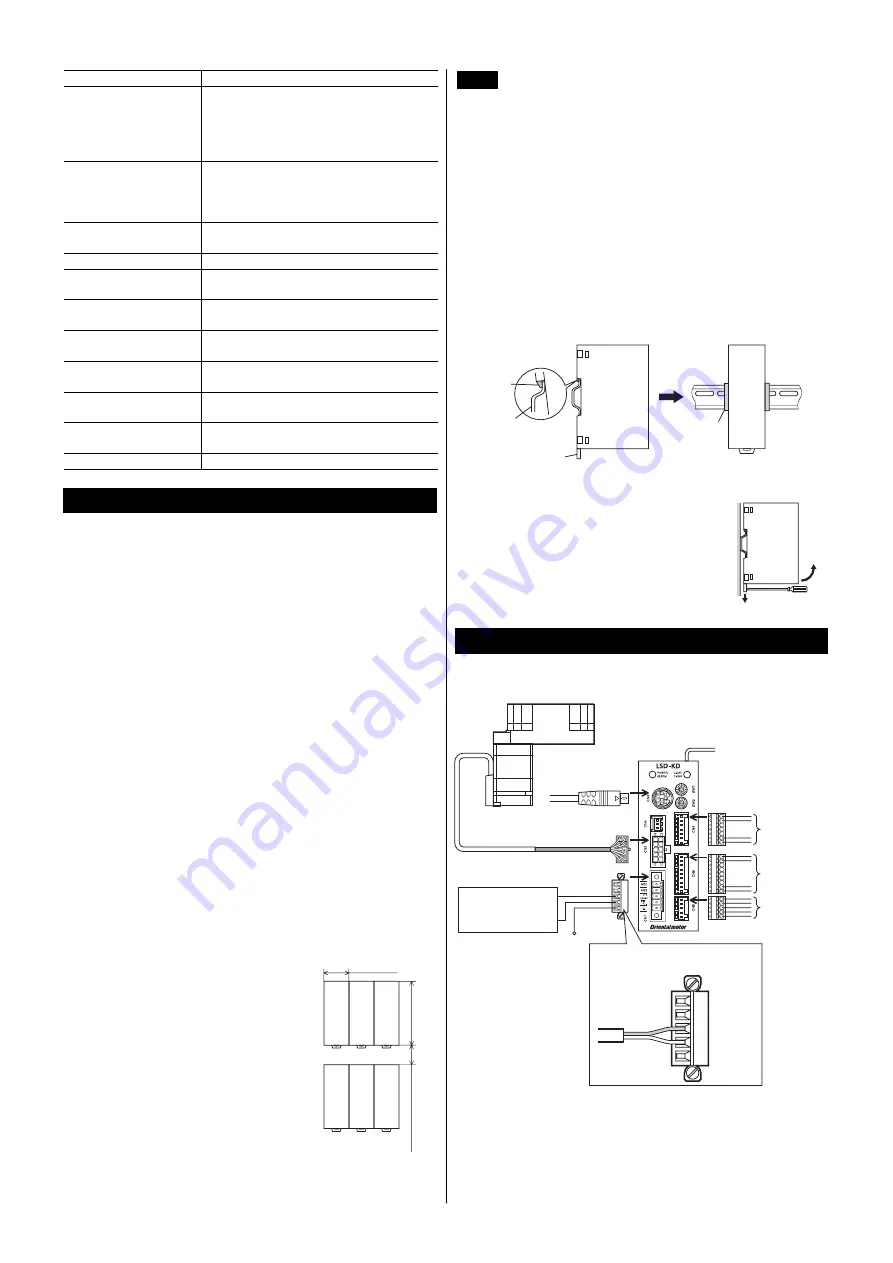
Installation method
Mount the driver to a 35 mm (1.38 in.) width
DIN rail. When installing two or more drivers
in parallel, it is possible to install them
closely in the horizontal direction.Provide a
minimum clearance of 50 mm (1.97 in.) in
the vertical direction.When installing three or
more drivers closely, the heat generation of
the inside drivers become high. Install the
less frequently used drivers toward the inside.
35 (1.38)
50 (1.97) or more
100 (3.94)
[Unit: mm (in.)]
Note
•
Install the driver in an enclosure whose pollution
degree is 2 or better environment, or whose degree
of protection is IP54 minimum.
•
Do not install any equipment that generates a large
amount of heat or noise near the driver.
•
Do not install the driver underneath the controller or
other equipment vulnerable to heat.
•
If the ambient temperature of the driver exceeds
50 °C (122 °F), improve the ventilation condition
such as providing forced cooling by using fans or
creating spaces between the drivers.
•
Be sure to install the driver vertically (vertical
position).
Pull down the driver’s DIN lever and lock it. Hang the hook at the
rear to the DIN rail, and push in the driver. After installation, secure
the both sides of the driver with the end plate.
Hook
DIN rail
DIN lever
㪜㫅㪻㩷㫇㫃㪸㫋㪼
Removing from DIN rail
Pull the DIN lever down until it locks using a flat
tip screwdriver, and lift the bottom of the driver
to remove it from the rail. Use force of about 10
to 20 N (2.2 to 4.5 lb.) to pull the DIN lever to
lock it. Excessive force may damage the DIN
lever.
Connection
Connection example
•
•
•
•
•
•
•
•
+24 VDC±5%
Cable for motor
Motor cable
+
GND
FG
Pay attention to the
polarity of the power
supply.
+24 VDC
GND
∗
2
∗
1
CN9:
Output signals
CN6/7: RS-485
Communication cable
CN8:
Input signals
CN5:
Sensor inputs
CN3
䋺
OPX-2A
or
MEXE02
CN2
CN1: DC power input
∗1
Power supply and FG connection cable: AWG24 to 16 (1.25to 0.2 mm2)
∗2
I/O signals connection cable: AWG26 to 20 (0.5to 0.14 mm2)