


14
Running/stopping the motor
Run/stop the motor by inputting operation control signals.
•
z
Operation
Since signals required to operate the motor are assigned to the control inputs
of the CN5, it is possible to perform operation without any change from
factory default.
CN5
Pin No.
Name
Initial value
Description
1
IN0 FWD input
This signal is used to rotate
a motor in the clockwise
direction.
2
IN1
REV input
This signal is used to rotate a
motor in the counterclockwise
direction.
3
IN2
STOP-MODE input
This signal is used to select
how to stop the motor.
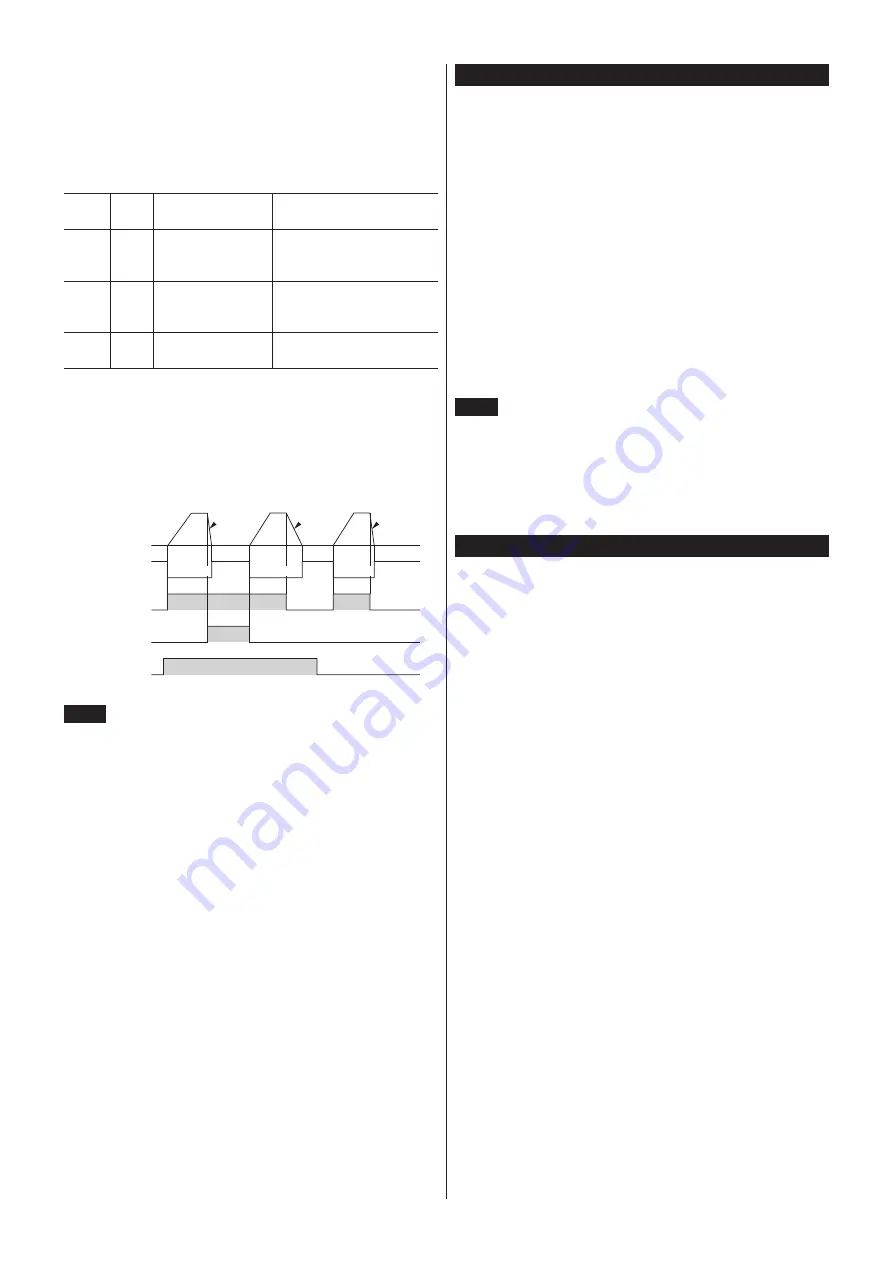
•
When the FWD input is turned ON, the motor rotates in the clockwise
direction. When the FWD input is turned OFF, the motor stops.
•
When the REV input is turned ON, the motor rotates in the
counterclockwise direction. When the REV input is turned OFF, the motor
stops.
•
If both the FWD input and REV input are turned ON, the motor stops
instantaneously.
ON
OFF
ON
OFF
ON
OFF
STOP-MODE
input
REV input
FWD input
Motor operation
Deceleration
stop
Instantaneous
stop
Instantaneous
stop
Electromagnetic
brake operation
Release
Release
Release
Note
When using the motor in vertical drive (gravitational
operation), although it depends on the load condition, if
operation is performed with the setting below, the motor
shaft may momentarily rotate in the reverse direction (about
one-fourth revolution of the motor output shaft) at the time of
starting/stopping the motor.
• When the set rotation speed is low
• When the acceleration time and deceleration time is long
•
z
Stop
When the STOP-MODE input is ON, the motor decelerates to a stop. When
the STOP-MODE input is OFF, the motor stops instantaneously.
Inspection
It is recommended that periodic inspections for the items listed below are
conducted after each operation of the motor.
If an abnormal condition is noted, discontinue any use and contact your
nearest Oriental Motor sales office.
Inspection item
•
The motor/gearhead mounting screws are not loose.
•
Check for any unusual noises in the motor bearings (ball bearings) or other
moving parts.
•
The bearing (ball bearing) and gear meshing parts of the gearhead are not
generating noise.
•
The motor/gearhead output shaft is not misaligned with the load shaft.
•
Are there any scratches, signs of stress or loose driver connections in the
cable?
•
Are the openings in the driver blocked?
•
The driver mounting screws and power connection terminal screws are not
loose.
•
Are there any strange smells or appearances within the driver?
Note
•
Conduct the insulation resistance measurement or dielectric
strength test separately on the motor and the driver.
Conducting the insulation resistance measurement or
dielectric strength test with the motor and driver connected
may result in damage to the product.
•
The driver uses semiconductor elements, so be extremely
careful when handling them.
Related products (sold separately)
Network converter
NETC01-CC
(CC-Link Ver.1.1 compatible)
NETC02-CC
(CC-Link Ver.2 compatible)
NETC01-M2
(MECHATROLINK-
Ⅱ
compatible)
NETC01-M3
(MECHATROLINK-
Ⅲ
compatible)
NETC01-ECT
(EtherCAT compatible)
When the
BLE
Series
FLEX
RS-485 communication type is used in a
CC-Link system or MECHATROLINK system, EtherCAT system while
connecting the driver via the network converter, the converted data from the
each communication protocol to the RS-485 communication protocol can be
sent to the driver.
Alarms and other data output from the driver, which normally conform
to the RS-485 communication protocol, can also be converted to each
communication protocol and sent to the master station accordingly.


