


10
Connection
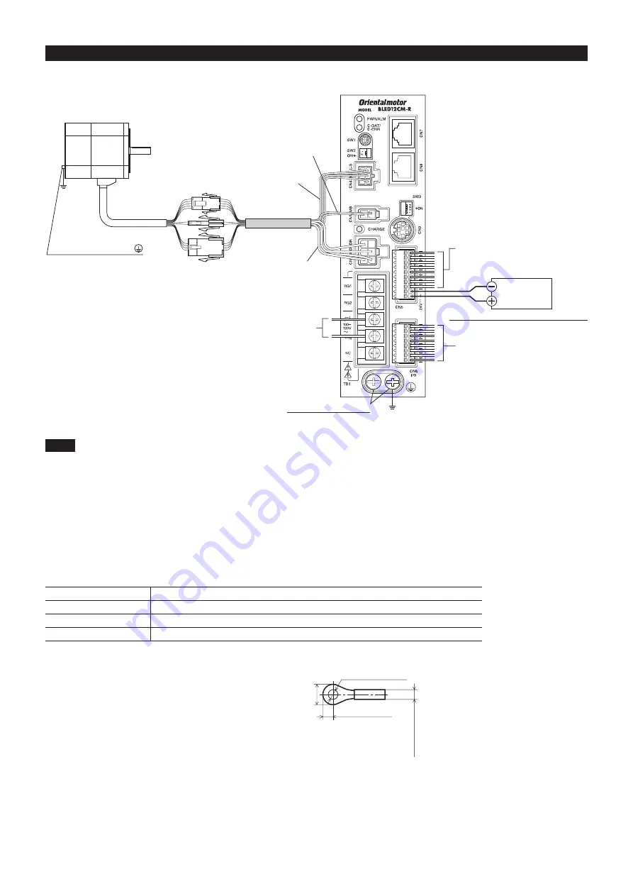
Connection example (electromagnetic brake motor)
24 VDC
power supply
Motor signal connector
Connect to CN4
Motor power connector
Connect to CN2
Electromagnetic brake connector
Connect to CN1
∗1
Input signals
Connect to CN5
External potentiometer or
External DC voltage
Input signal common (0 V)
Output signals
Connect to CN6
Grounding
Connection cable
∗2
Motor cable
Main power supply
Connect to TB1
Protective Earth Terminal
Be sure to ground.
Protective Earth Terminal
Be sure to ground.
Grounding
∗1
Electromagnetic brake type only
∗2
Check the USER MANUAL for details on the connection.
Connect in accordance with the polarities.
Note
•
Have the connector plugged in securely. Insecure connections may cause malfunction or damage to the motor or driver.
•
When connecting the 24 VDC power supply, check the indication of the driver case and pay attention to the polarity of the power
supply. Reverse-polarity connection may cause damage to the driver.
•
Do not wire the power supply cable of the driver in the same cable duct with other power lines or motor cables. Doing so may cause
malfunction due to noise.
•
When cycle the power or plugging/unplugging the connector, turn off the power and wait for the CHARGE LED to turn off before doing
so. Residual voltage may cause electric shock.
•
When installing the motor to a moving part, use an accessory flexible cable offering excellent flexibility. Refer to the USER MANUAL
for details.
Connecting the power supply (TB1)
Connect the power cable to the main power supply input terminals (TB1) on the driver.
Input power supply
Connecting method
Single-phase 100-120 V Connect the live side to terminal L, and the neutral side to terminal N.
Single-phase 200-240 V Connect the live side to terminal L1, and the neutral side to terminal L2.
Three-phase 200-240 V Connect the R, S and T phase lines to the L1, L2 and L3 terminals, respectively.
•
z
Power connection terminal and cable
Applicable crimp terminal: Round crimp terminal with insulation cover
Thread size of terminal: M3.5
Tightening torque: 1.0 N·m (8.8 lb-in)
Applicable lead wire: AWG18 to 14 (0.75 to 2.0 mm
2
)
Conductive material: Use only copper wire.
3.8 (0.15) or less
7.2 (0.28) or less
6.2 (0.24) or less
after crimping
Ø3.6 (0.14) or more
Unit: mm (in.)
Circuit breaker
Be sure to connect a circuit breaker to the power line of the driver to protect the primary circuit.
Rated current of protective device: Single-phase input 10 A, three-phase input 5 A
Circuit breaker: Mitsubishi Electric Corporation NF30


