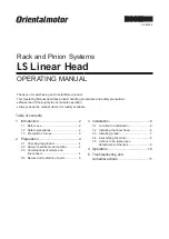
Installation
−7−
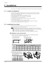
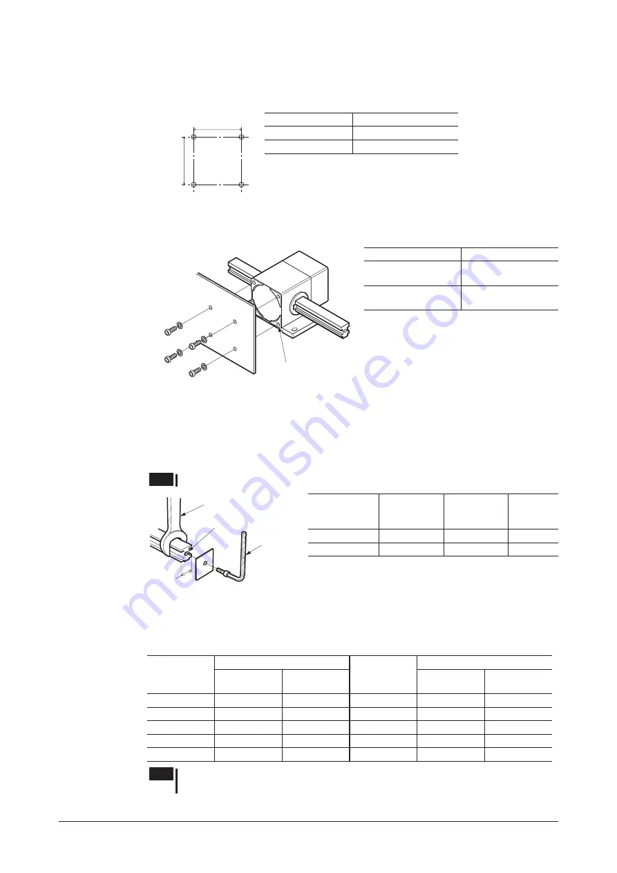
Installation using mounting holes on the front face
1.
Drill mounting holes or tapped holes in the metal plate used to install the linear head.
The same machining dimensions for mounting holes apply to both the B type and F type.
J±0.5 mm (0.02 in.)
J±0.5 mm (0.02 in.)
Linear head model
J [mm (in.)]
2LS
type
47 (1.85)
4LS
type
62 (2.44)
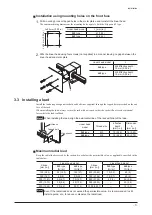
2.
Affix the linear head using four screws (not supplied) in a manner leaving no gaps between the
linear head and metal plate.
L
Linear head model
L
2LS
type
M6 Effective depth
10 mm (0.39 in.)
4LS
type
M8 Effective depth
10 mm (0.39 in.)
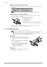
3.3 Installing a load
Install the load using hexagonal socket head bolts (not supplied) through the tapped holes provided on the end
face of the rack.
When installing the load, always secure the rack with a wrench so that the rack will not receive rotational
force while the load is affixed.
Note
When installing the load, align the axial centerline of the rack with that of the load.
Wrench
Tapped hole
A
Hex wrench
Linear head
model
Thread size
Effective
depth
[mm (in.)]
Dimension
A
[mm (in.)]
2LS
type
M5
10 (0.39)
16 (0.63)
4LS
type
M8
15 (0.59)
20 (0.79)
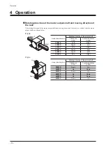
Maximum radial load
Keep the radial load received by the rack end to or below the permissible value, as applicable, specified in the
table below.
Stroke
[mm (in.)]
Linear head model
Stroke
[mm (in.)]
Linear head model
2LS
type
[N (lb.)]
4LS
type
[N (lb.)]
2LS
type
[N (lb.)]
4LS
type
[N (lb.)]
100 (3.94)
55 (12.3)
120 (27)
600 (23.62)
15 (3.3)
40 (9)
200 (7.87)
40 (9)
90 (20)
700 (27.56)
12 (2.7)
40 (9)
300 (11.81)
30 (6.7)
70 (15.7)
800 (31.50)
8 (1.8)
25 (5.6)
400 (15.75)
25 (5.6)
60 (13.5)
900 (35.43)
─
20 (4.5)
500 (19.69)
20 (4.5)
50 (11.2)
1000 (39.37)
─
15 (3.3)
Note
Even if the radial load does not exceed the permissible value, it is recommended to still
install a guide, etc., to reduce or disperse the radial load.

