Installation
−6−
3 Installation
This section covers the linear head’s installation location and method, as well as the method of installing a load.
3.1 Location for installation
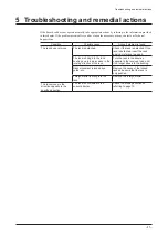
The linear head is designed and manufactured for use as a built-in component in industrial equipment.
Install it in a well-ventilated place satisfying the following conditions, where the product can be easily
accessed for the purpose of inspection.
•
Inside an enclosure installed indoors (with ventilation hole provided)
•
Ambient temperature: –10 to +50 °C (+14 to +122 °F) (non-freezing)
•
Ambient humidity: 85% or less (non-condensing)
•
Area that is free of explosive atmosphere or toxic gas (such as sulfuric gas) or liquid
•
Area not exposed to direct sun
•
Area free of excessive amount of dust, iron particles or the like
•
Area not subject to splashing water (rains, water droplets), oil (oil droplets) or other liquids
•
Area not subject to continuous vibration or excessive shocks
3.2 Installing the linear head
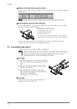
Install the linear head using the mounting feet, or mounting holes provided on the front face.
Securely affix the linear head to a grounded metal plate.
Note
•
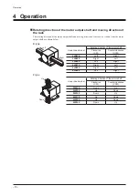
When installing the linear head in the direction allowing the rack to move up and down,
take appropriate measures to prevent dropping and collision of the rack. If the rack drops,
the tooth surface, pinion and gear of the rack may be damaged.
•
If you are using a photomicrosensor, install it after installing the lineard motor.
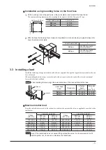
Installation using a mounting foot
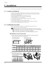
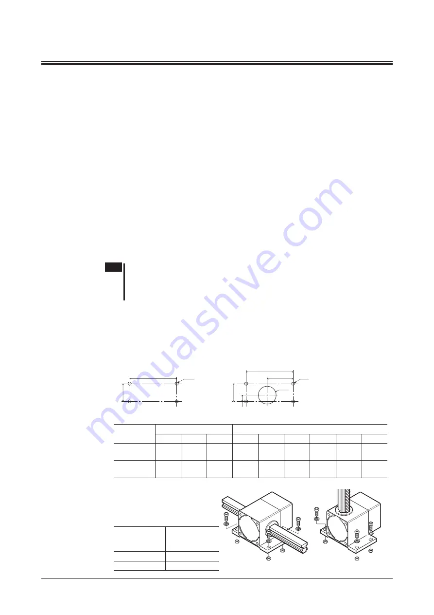
1.
Drill mounting holes or tapped holes in the metal plate used to install the linear head.
With the F type, also drill a hole (G) for guiding the rack.
•
Machining dimensions for
mounting holes for B type
•
Machining dimensions for
mounting holes for F type
A±0.5 mm (0.02 in.)
B±0.5 mm (0.02 in.) ØH
D±0.5 mm (0.02 in.)
C
E±0.5 mm (0.02 in.)
F
ØI
ØG
Linear head
model
B type [mm (in.)]
F type [mm (in.)]
A
B
ØH
C
D
E
F
ØG
ØI
2LS
type
35
(1.38)
92
(3.62)
6.5
(0.26)
12.5
(0.49)
35
(1.38)
92
(3.62)
51
(2.01)
35
(1.38)
6.5
(0.26)
4LS
type
30
(1.18)
100
(3.94)
8.5
(0.33)
15
(0.59)
30
(1.18)
100
(3.94)
58
(2.28)
45
(1.77)
8.5
(0.33)
2.
Affix the linear head using four
screws (not supplied) in a manner
leaving no gaps between the linear
head and metal plate.
•
B type
•
F type
Linear head
model
Mounting foot
thickness
[mm (in.)]
2LS
type
9 (0.35)
4LS
type
12 (0.47)

