


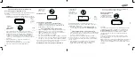
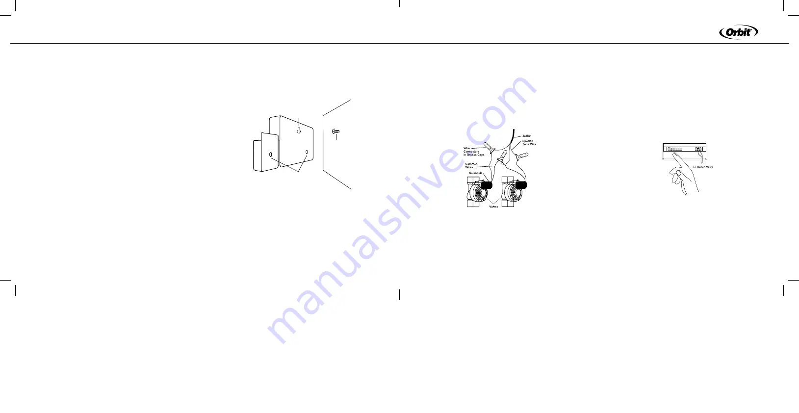
• Each valve has two wires. One wire is to be connected as
the common. The common wires for all the valves can be
connected together to one common wire going to the timer.
The other valve wire is to be connected to the specific station
wire that will control that valve [See Figure 19].
• All wires should be joined together using wire nuts, solder, or
vinyl tape. For additional protection to waterproof connections
a WaterMaster
®
grease cap can be used.
• To avoid electrical hazards, only one valve should be connected
to each station.
figure 19: Wiring Valves
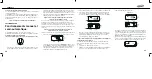
Connecting Valve Wires to the timer
• Remove cover by sliding it down.
• Determine which valve you want to connect to which station.
Connect each valve wire to its station terminal (labeled 1-6 or
1-12) by inserting the bare wire.
• It may be necessary to “open” the terminal to allow for
wire insertion or removal. To do this, simply take a Phillips
screwdriver and turn the screw two to three turns counter
clockwise. After inserting wire turn the screw clockwise. Do
not over tighten.
• Connect the common wire to the terminal labeled “com” [See
Figure 20].
figure 20: Connecting Valve Wires
13
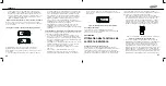
To program the Transmitter:
• While holding the Transmitter in one hand, press and release
the transmitter program button found to the right of the RAIN
DELAY button. The red indicator light on the Timer will turn on.
Press the off button on the Transmitter. The Transmitter will
beep three times and the red indicator light on the Timer will
blink, indicating the program coding is complete.
Section Six
InStALLAtIOn
timer Location
• Select a location near a standard electrical outlet. Avoid using
an outlet controlled by an On/Off switch.
• The timer should not be exposed to the weather or operated at
temperatures below 32° or above 113° Fahrenheit. (0° c + 45° c)
• Installation works best inside a garage or protected area. The
Timer should not be mounted outdoors.
Note: The distance that the Transmitter and Timer will operate at is
approximately 200 feet line of sight. This distance can be affected by
obstacles such as walls, automobiles, metal siding, etc. To achieve
the maximum amount of range, mount the Timer as high on the wall
as is convenient for operation and service.
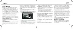
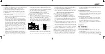
Mounting the timer
• Screw a No. 8 screw at eye level leaving the screw head
extended out from the wall about 1/8 inch. Use expanding
anchors in plaster or masonry if necessary.
• Slip the keyhole in the back of the timer over the extended
screw.
• Screw a No. 8 screw through each of the two holes at the
bottom of the timer box into the wall [See Figure 18].
• Install two AA batteries, and re-enter the time and date
as required.
figure 18: Mounting the timer
Wiring the Electric Valves
• If the distance between the timer and valves is under 700 feet,
use WaterMaster
®
sprinkler wire or 20 gauge plastic jacketed
thermostat wire to connect the timer to the valves. If the
distance is over 700 feet, use 16 gauge wire. The wire can
be buried in the ground; however, for more protection wires
can be pulled through PVC pipe and buried underground. Be
careful to avoid burying the wires in locations where they could
be damaged by digging or trenching in the future.
12
EnGLISH
Keyhole
Screwholes
No. 8 Screw
Wall


