-
46
-
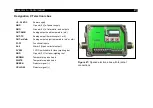
The industrial process interface provides the following inputs and outputs:
Name
Description
max range
1)
/ status
A IN 1 / 2
Analog input 1 and 2
0-10 V
2)
D IN 1
Digital input
(active-
low = 0…0,6 V)
24 V
AO1 / 2 / 3
Analog output 1, 2 and 3
Alarm output 1, 2 and 3
0/4-20 mA
DO1 / 2/ 3
Relay output 1, 2 and 3
3)
open/ closed (red LED on) / 0...30 V, 400 mA
FS
Fail-safe relay
open/ closed (green LED on)/ 0...30 V, 400 mA
1)
depending on supply voltage; for 0-20 mA on the AO the PIF has to be powered with min. 5V < (1.5 + working resistance * 0.021) <
24 V; Example: R
Load
= 500 ohm
→ U
min
= 1.5 + 500 * 0.021 = 12 V, R
Load
= 100 ohm
→ U
min
= 1.5 + 100 * 0.021 = 3.6 V
→ min. 5 V
2)
the AI is designed for max. 24 V, the voltage level above 10 V is not interpreted
3)
active if AO1, 2 or 3 is/ are programmed as alarm output
The alarm output can be configured as a threshold between
0-4 mA
for
no alarm
and between
10-20 mA
as
alarm
. For values outside the respective range, the relay does not switch on the DO.
Содержание Top-down GIS
Страница 1: ...Operators Manual Top down GIS Glass Inspection System ...
Страница 5: ... Table of contents 5 Appendix A Control cabinet 43 ...
Страница 11: ... Technical Data 11 Figure 1 Dimensions mm shutter system ...
Страница 12: ... 12 Figure 2 Dimensions mm switch cabinet ...
Страница 19: ... Technical Data 19 CT G5L SF optics ...
Страница 34: ... 34 Figure 16 Linescan in PIX Connect software ...
Страница 43: ... Appendix A Control cabinet 43 Appendix A Control cabinet Figure 24 Wiring diagram of control cabinet ...
Страница 48: ...Top down GIS MA E2021 07 A ...


