background image

NOTE: 

Port  Forwarding  must  be  configured  on  Router  2. 

This  procedure  varies  on  different  devices  and  instructions 
should be available on Router 2 user manual. 

4.7. Updating the firmware

If your device firmware version doesn’t match to software’s 
firmware  version  while  connecting  to  device  via  LPA 
software  you’ll  be  asked  to  update  your  device.  If  update 
request  pops-up,  but  you  want  to  keep  current  firmware 
and  use  LPA  software,  you  must  use  software  compatible 
with that firmware version.  

NOTE: 

Compatible  software  had  been  delivered  with 

device. If lost contact us (

[email protected]

) 

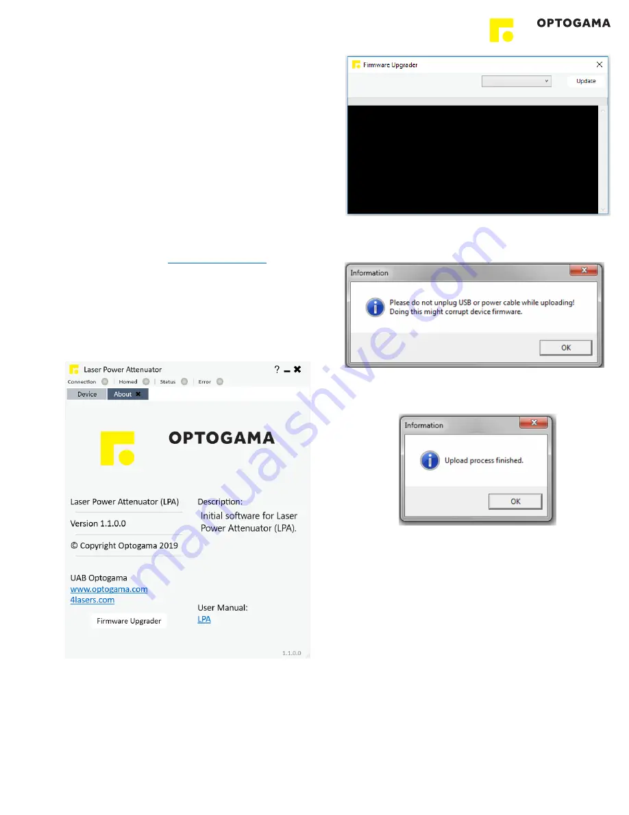
In order to update your device or rewrite device firmware - 

USB cable

 must be used (update through RS232 cable is 

not available).  

1. Click button 

“Firmware Upgrader”

 in the About tab of 

MRO software: 


2. In  the  opened  window  press  “

Update

”  button.  You  will 

be asked if you really want to update device: 


After  a  warning  device 

motors  will  be  shut  down

  and 

update will start: 


3. Update  should  be  done  in  about  a  minute.  If  everything 

went successfully message box like this should pop-up: 


Now you’re ready to go. 

15

Содержание MRO

Страница 1: ...MANUAL v3 3 MRO MOTORISED ROTATOR KEY for DISCOVERIES ...

Страница 2: ...lient operating systems 8 4 4 Installing the software 8 4 5 Using the software 10 4 5 1 Connection 10 4 5 2 Settings calibration 10 4 5 3 Main window 11 4 6 Ethernet connection 12 4 6 1 About TCP IP pMROocol 12 4 6 2 Client and Server Connection 12 4 6 3 Ethernet con fi guration using MRO software 13 4 6 4 Ethernet connection using MRO software 13 4 6 5 Ethernet con fi guration using commands 14 4...

Страница 3: ...damage to the device components connected to it or operator NOTE Sections marked with this symbol indicate important information on rotator or about this manual Due to constant development of our products we reserve the right to make changes in the production line without further notice Up to date information is available at our website www optogama com If there are any further questions please co...

Страница 4: ... make sure the device is installed correctly and well adjusted and all cover stickers are removed Protective measures should be considered if necessary Electrical safety requirements must be complied while operating this device CAUTION High laser output power may damage or destroy optical elements CAUTION The device is meant to be used with a collimated beam Users take full responsibility when usi...

Страница 5: ...ht ZO L 4 wave plate zero order quarter wave plate This setup is used to convert linearly polarised light into circularly polarised and vice versa NOTE Homing is required CAUTION Before increasing laser power make sure the device is aligned and there is no beam cut It may damage optical elements 2 1 Features and advantages Compact design High resolution 175543 µsteps in 360 deg rotation High accur...

Страница 6: ...8 mm LIDT coating 10 J cm2 10 ns 1064 nm Close to open time 0 to 45 deg 0 2 sec Resolution 175 543 µsteps in full rotation 21 943 µsteps in 45deg rotation 0 002 deg 7 2 arcsec 0 035 mrad Accuracy 10 µsteps 0 02 deg Motor 2 phase stepper motor 200 steps with 256 µstepping Available coatings A Standard wavelenghts nm 1550 780 355 1064 400 343 1030 532 266 800 515 257 MRO rotator Controller Lenght 37...

Страница 7: ... error please connect PC for further troubloushooting BUTTONS functions CW MROation Push button to rotate clock wise CCW MROation Push button to rotate counter clock wise Home Tap Tap both buttons to home the device Calibrate Reset Hold 2 to 6 s Hold both buttons from 2 to 6 seconds to de fi ne calibrate current position as 0 deg or reset it Homed and Status LED s will start blinking when it is ri...

Страница 8: ...t to comply with the slew rate requirements for data transmission 3 7 What s in the box Standard kit includes 1 Motorised rotator MRO 2 Controller SMC 3 Software LPA 4 Power supply DC 12V GST60A12 P1J 5 USB cable 1 5 m NOTE Other accessories must be purchased separately 4 Software 4 1 Minimum Hardware requirements recommended 4 2 System requirements To install the application you must have adminis...

Страница 9: ...Install 4 Setup will fi nish the installation 5 Press Finish to end the installation Connect the device and controller via HD 15 cable 6 Connect the PC and controller via USB or RS232 cable 7 Plug in power supply to controller and AC adaptor to wall outlet 8 The device will be detected and con fi gured 9 The device installation is complete 9 ...

Страница 10: ...vice will not be visible NOTE Rotator will be seen as MROxxx for ex MRO001 4 5 2 Settings calibration 11 Using rotator for the fi rst time the calibration is required The information window will appear 12 For MRO calibration move your mouse to the left side of the window on a gear symbol from the sliding menu and select Settings Settings menu will appear 13 To succeed calibration please follow cal...

Страница 11: ...11 Preset buttons Click Edit to add or edit preset t values for a quick change Settings Select this icon to open calibration and settings window Angle value in deg Enter required power value Press Enter Power Slider Move the slider to change angle Buttons for incremental change Click grey button to rotate clockwise or counter clockwise Save as preset Save current angle as preset button in required...

Страница 12: ...creates a virtual IP port and the network hardware and software are responsible for routing data in and out of each virtual IP port 4 6 2 Client and Server Connection TCP IP connection works in a manner like a telephone call where someone has to initiate the connection by dialling the phone At the other end of the connection someone has to be listening for calls and then pick up the line when a ca...

Страница 13: ...nput Subnet Mask address It is fi lled automatically if only one network interface is available 3 5 Input Network Port By default it is 555 but you can choose any up to 65535 NOTE Default Network port 555 Con fi guration is complete 4 6 4 Ethernet connection using MRO software 1 Connect MRO controller via Ethernet cable RJ45 plug 2 Open MRO software 3 Open Ethernet Connection and select your Netwo...

Страница 14: ...rough Router whose IP address is 192 168 30 100 and both devices are connected to it If everything is con fi gured correctly TCP Server during listening of Port 555 should get a request of connection from MRO device 2 MRO and other device communication from di ff erent networks over internet MRO is a Client and another device is a Server In this case both devices are on different networks and the ...

Страница 15: ... use software compatible with that fi rmware version NOTE Compatible software had been delivered with device If lost contact us sales optogama com In order to update your device or rewrite device fi rmware USB cable must be used update through RS232 cable is not available 1 Click button Firmware Upgrader in the About tab of MRO software 2 In the opened window press Update button You will be asked ...

Страница 16: ...lue in percentages MRO PWR MRO PWR _45 125 MRO PWR _X XXX MRO PWR _X XXX When used in attenuator mode Command used to set a new power value in percentages MRO PWR _10 MRO PWR_10 000 MRO PWR _45 1 MRO PWR_45 100 MRO PWR _0 07 MRO PWR_0 070 MRO ANG MRO ANG_X XXX Command used to get the current angle value in degrees MRO ANG MRO ANG_22 143 MRO ANG _X XXX MRO ANG_X XXX Command used to set the angle va...

Страница 17: ...o get controller physical buttons state 1 disabled 0 enabled MRO LDF MRO LDF Command used to load default settings Device after this command must be 1 Homed 2 Recalibrated Ethernet settings MRO NIP _x x x x MRO NIP_x x x x Command used to set Client MRO IP address in local network MRO NIP _192 168 30 140 MRO NIP_192 168 30 140 MRO NIP MRO NIP_x x x x Command used to get Client MRO IP address in lo...

Страница 18: ...11 motor is stand still bit12 motor target velocity reached bit13 target position reached bit14 homing procedure was run after the reset bit15 device calibration is done More info on pg 19 MRO STATUS MRO 1_0 MRO STATUS MRO 0_0 MRO STATUS MRO 1_2 MRO WL MRO WL_XXX Command used to get the design wavelength MRO WL MRO WL_355 MRO FW MRO _Firmware version Command used to get fi rmware version MRO FW MR...

Страница 19: ...nder voltage on the motor driver charge pump The driver is disabled in this case Bit6 external memory error working calibration data may be corrupted Flag is set if there was an error reading data from EEPROM Bit7 reset has occurred Indicates that the motor driver has been reset since the last read access to STATUS All registers have been cleared to reset values Bit8 Bit9 left right limit switch i...

Страница 20: ...5 2 Serial communication example in Python 20 ...

Страница 21: ...6 Technical information 6 1 MRO drawings 21 ...

Страница 22: ...R INFORMATION ONLY NOT FOR MANUFACTURING PURPOSES Created by Finish DWG No Title Scale Sheet A3 1 1 LPA controller Anodized Aluminium 2019 03 25 1 1 LPA controller Optogama 31 53 125 50 5 74 5 31 22 M3x0 5 3 2 holes 24 DC Power 12V USB Type B PC connection RS 232 HD 15 LPA connection 22 ...

Страница 23: ...6 3 Power supply 23 ...

Страница 24: ...6 4 RS232 cables 24 ...

Страница 25: ...OPTOGAMA UAB Mokslininku str 2A LT 08412 Vilnius Lithuania 37052194884 sales optogama com www optogama com ...

Отзывы: