DD4MR-FX
11 / 24
rev. 2.1
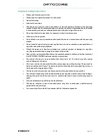
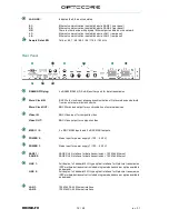
Front Panel
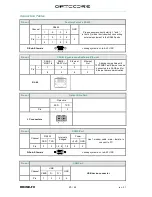
Word Clock LED:
Indicates the selected word clock source:
INT:
Internal word clock – The device is a system master
BNC:
External word clock via BNC WC Input
NET:
Word clock received from network
Status LEDs of MADI Input and Output 1 and 2:
INPUT SYNC
Indicates the status of MADI Input
LED ON: Valid MADI frame is present
LED OFF: No MADI signal is present or signal is not valid
OUTPUT ON
Indicates the configuration of MADI Output
MADI
Indicates if there is MADI protocol active
56 / 64
MADI format and number of channels
LED ON: 64 CH = single speed (AES10-2003)
LED OFF: 32 CH = double speed (AES10-2003)
1 / 2 / 3 / 4 / 5 / 6 / 7 / 8
Signal status of the eight channel groups, each group representing eight audio
channels:
LED ON: Signal present
LED OFF: No signal present
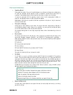
AUDIO LINK:
Indicates the audio link status
SL1: Communication is established via SANE 1 (rear panel)
SL2: Communication is established via SANE 2 (rear panel)
OL1: Communication is established via Optocore LINK 1 (rear panel)
OL2: Communication is established via Optocore LINK 2 (rear panel)
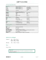
System status
Master LED:
Indicates the master unit
OPTO LED:
Optocore communication is established
SANE LED:
SANE communication is established
Device ID Display:
Indicates the identification number of the device
HEALTH LED:
Green: Power supply is correctly working, temperature is below the limit
PWR 1 LED:
Power supply 1 is working correctly
PWR 2 LED:
Power supply 2 is working correctly
USB plug and LED:
USB connection for remote control and update via PC
Green: Indicates data activity
RS232 plug:
D-Sub-9 RS232 connection for remote control and update via PC
Содержание DD4MR-FX
Страница 2: ...Page intentionally left blank ...
Страница 8: ...Page intentionally left blank ...


