DD4MR-FX
12 / 24
rev. 2.1
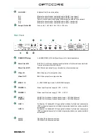
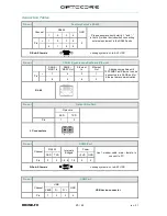
LAN LINK:
Indicates the Ethernet link status
S1:
Ethernet communication is established via SANE 1 (rear panel)
S2:
Ethernet communication is established via SANE 2 (rear panel)
UP:
There is other device with physical Ethernet port enabled on the network
L1:
Ethernet communication is established via LAN 1 (rear panel)
L2:
Ethernet communication is established via LAN 2 (rear panel)
Sample Rate LED:
Yellow: 44,1 / 48 / 88,2 / 96 / 176,4 / 192 kHz
Rear Panel
RS485/GPIO plug:
4 x RS485/RS422 (D-Sub-9) auxiliary port for data transmission
Word Clock IN:
BNC Word clock input allowing synchronization of Optocore devices/network
from an external word clock source
Word Clock OUT:
BNC Word clock output for synchronization of external devices
Video IN:
BNC Video input for composite video
Video OUT:
BNC Video output for composite video
MADI 1 / 2:
2 x BNC MADI inputs and 2 x BNC MADI outputs
POWER 2:
Mains input for power supply 2 (100 … 240 V)
POWER 1:
Mains input for power supply 1 (100 … 240 V)
SANE 1:
SANE RJ-45 interface for data transm 100 Mbit Ethernet
SANE 2:
SANE RJ-45 interface for data transm 100 Mbit Ethernet
LINK 1:
Full-duplex, full bandwidth LC-type optical interface for Optocore transmission
(SFP multimode transceiver included, singlemode transceiver option available
on demand)
LINK 2:
Full-duplex, full bandwidth LC-type optical interface for Optocore transmission
(SFP multimode transceiver included, singlemode transceiver option available
on demand)
LAN 1:
100 Mbit RJ-45 Ethernet interface
LAN 2:
100 Mbit RJ-45 Ethernet interface
Содержание DD4MR-FX
Страница 2: ...Page intentionally left blank ...
Страница 8: ...Page intentionally left blank ...


