


LTDVE8CH– INSTRUCTIONS MANUAL
26
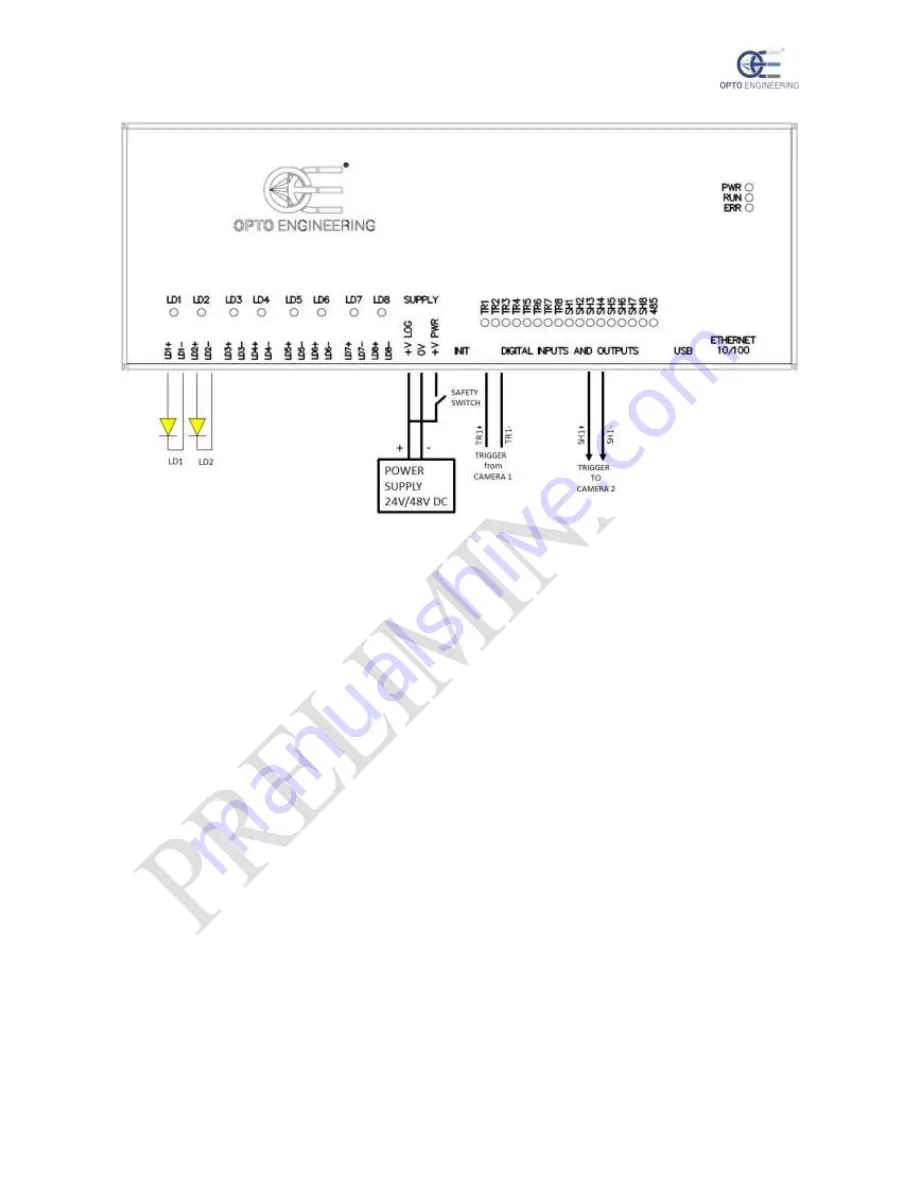
Figure 11: example schematic #2
As shown, the power and logic supplies are derived from a common power supply.
If required for the application, a safety switch may be included in the circuit to cut off supply to the
power stages in order to protect the end user from photo-biological hazard. That switch would be
appropriately placed on the machine chassis.
The controller is triggered by camera 1 using one of the eight available synchronization inputs.
Camera 2 is triggered by the controller using one of the eight available synchronization outputs.
Generally, it is not possible to provide the details of the connections to the cameras because these are
often vendor specific. Please see the camera hardware manual for more information.
14. Operation
There are several ways to configure the controller.
A first option is to use the serial RS485 interface. To support this interface the controller implements
a subset of the Modbus/RTU slave protocol. A second option is to use the Ethernet interface.
Supported Ethernet speeds are 10 Mbit/s and 100 Mbit/s with auto negotiation. The Ethernet interface
allows to configure the controller using the Modbus/TCP slave protocol, the Modbus/UDP slave
protocol or the HTTP protocol. For supporting the latter, the controller provides an internal web server
accessible by most common web browsers.
In the next sections, an overview of the Modbus/RTU, Modbus/TCP and Modbus/UDP protocols is
given.
14.1. Operation with Modbus
The Modbus/RTU, Modbus/TCP and Modbus/UDP protocols are supported by most programmable
logic controllers (PLCs) with a suitable communication port. The controller can also be configured
by any PC with a proper interface.


