


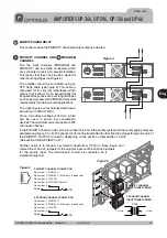


Fuse
O U T P U T S
0
50V
FAIL
SURETY
PAGING
70V 100V
16 Ω
8Ω
4Ω
24V
FAN
POWER
SUPPLY
230V
50/60 Hz
I N P U T / O U T P U T C O N T A C T S
1
2
3
4
5
6
7
8
9
PRIORITY
CTRL. INPUT
GND
PRIORITY
INPUT
PRIORITY
OUTPUT
PROGRAM
INPUT
PROGRAM
OUTPUT
ON
OFF
POWER AMPLIFIER
240W RMS (312W IHF)
U P - 2 4 6
Engineered in EU (Spain)
Made in China
OPTIMUS S.A.
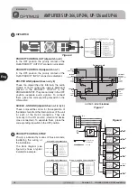
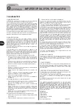
PRI-PRO RJ CONNECTION
6. PRIORITY
8.
METAL
SHIELD
GND
(WHEN BALANCED)
7
8
6
5
3
2
1
DIPSWITCH CONFIGURATION
ON
OFF
PRI-PRO
LINK
SHIELD-GND
LINK
7. Priority ctrl. in
6. Audio C
5. Audio H
4. Priority in
8. Priority ctrl. out
3. Priority out
2. Program in
1. Program out
SURVEILLANCE
SURVEILLANCE RJ CONNECTION
1. OSC IN
2. NC
3. OSC OUT 1
4. PROTECT
5. OSC OUT 2
6. PRI OUT
7. +24VDC OUTPUT
8.
METAL
SHIELD
GND
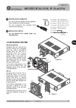
24V
FAIL
O U T P U T S
0
50V 70V 100V
4Ω 8Ω 16Ω
SURETY PAGING
DIPSWITCH
PRIORITY CONTROL OUT (dipswitch no. 8)
PRIORITY CONTROL IN (dipswitch no. 7)
PRI-PRO LINK (dipswitches no. 5 y 6)
SHIELD - GND LINK (dipswitches no. 1,2,3 y 4)
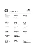
PRIORITY CONTROL STRIP
In the OFF position, the priority contact of the
RJ45 PRIORITY OUTPUT connector is disabled.
In the OFF position, the priority contact of the
RJ45 PRIORITY INPUT connector is disabled.
These two dipswitches link internally the audio
signals H and C (when the input is balanced)
present in the PRIORITY OUTPUT to the
PROGRAM INPUT.They are normally in the OFF
position (separate audio signals). To connect
them, place the corresponding dipswitch in the
ON position.
These 4 dipswitches allow for the separation of
the cable shield from the internal mass of the unit
for each of the RJ-45 connectors. They are
normally in the ON position (shield and device
mass connected). To separate them, place the
corresponding dipswitch in the OFF position.
Priority is activated by means of these contacts,
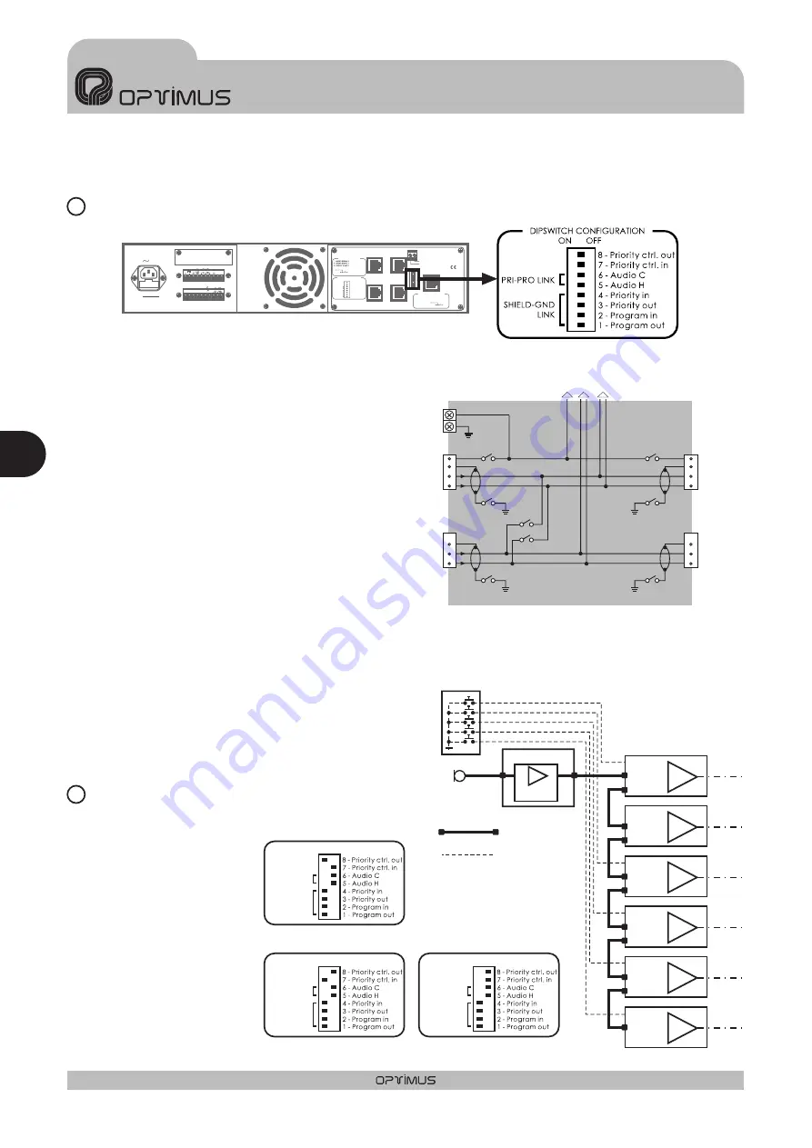
facilitating the wiring of
the installation.
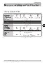
The block diagram (see
figure 8) shows a typical
installation example.
12
13
OUTPUT - INPUT DIAGRAM
Figure 6
Figure 7
Figure 8
zone 1A
zone 1B
zone 2
zone 3
zone 4
zone 5
UP-126
PM-612/0
MIC
ZONES SELECTOR
C610PAL
UP-126
UP-126
UP-126
UP-126
UP-126
Priority input
RJ connector
Priority input
RJ connector
Priority input
RJ connector
Priority input
RJ connector
Priority input
RJ connector
Priority input
RJ connector
Priority control
input contact
Priority control
input contact
Priority control
input contact
Priority control
input contact
Priority control
input contact
Priority control
input contact
Priority output
RJ connector
Priority output
RJ connector
Priority output
RJ connector
Priority output
RJ connector
Priority output
RJ connector
8 pins RJ45
connectors
Priority
PRI-PRO LINK
SHIELD-GND
LINK
ON
OFF
Zone 2, 3, 4 and 5 UP-126 configuration
PRI-PRO LINK
SHIELD-GND
LINK
ON
OFF
Zone 1B
configuration
UP-126
PRI-PRO LINK
SHIELD-GND
LINK
ON
OFF
Zone 1A
configuration
UP-126
To power unit
AUDIO H
PRIORITY CTRL.
PRIORITY
CONTROL INPUT
GND
PRIORITY
INPUT
PROGRAM
INPUT
SHLD
SHLD
AUDIO H
SW 7
SW 8
SW 4
SW 3
SW 5
SW 2
SW 1
SW 6
AUDIO C
AUDIO C
PROGRAM
OUTPUT
SHLD
AUDIO H
AUDIO C
AUDIO H
PRIORITY CTRL.
PRIORITY
OUTPUT
SHLD
AUDIO C
Eng
AMPLIFIERS UP-366, UP-246, UP-126 and UP-66
E N G L I S H
1 8
UP-366, UP-246, UP-126 and UP-66
Version 1.1


