0
50V
70V
100V
4
Ω
8
Ω
16
Ω
SPEAKERS
LINE
OUTPUT
POWER
STAGE
PRIORITY
CONTROL
INPUT
MASTER
PRIORITY
MASTER
PROGRAM
PRI-PRO
LINK
PROGRAM
PRIORITY
PROTECTION
PRIORITY OUTPUT
PRIORITY INPUT
PROGRAM OUTPUT
PROGRAM INPUT
SURETY
PAGING
FAIL
SURVEILLANCE
Priority & Control Signal
Audio
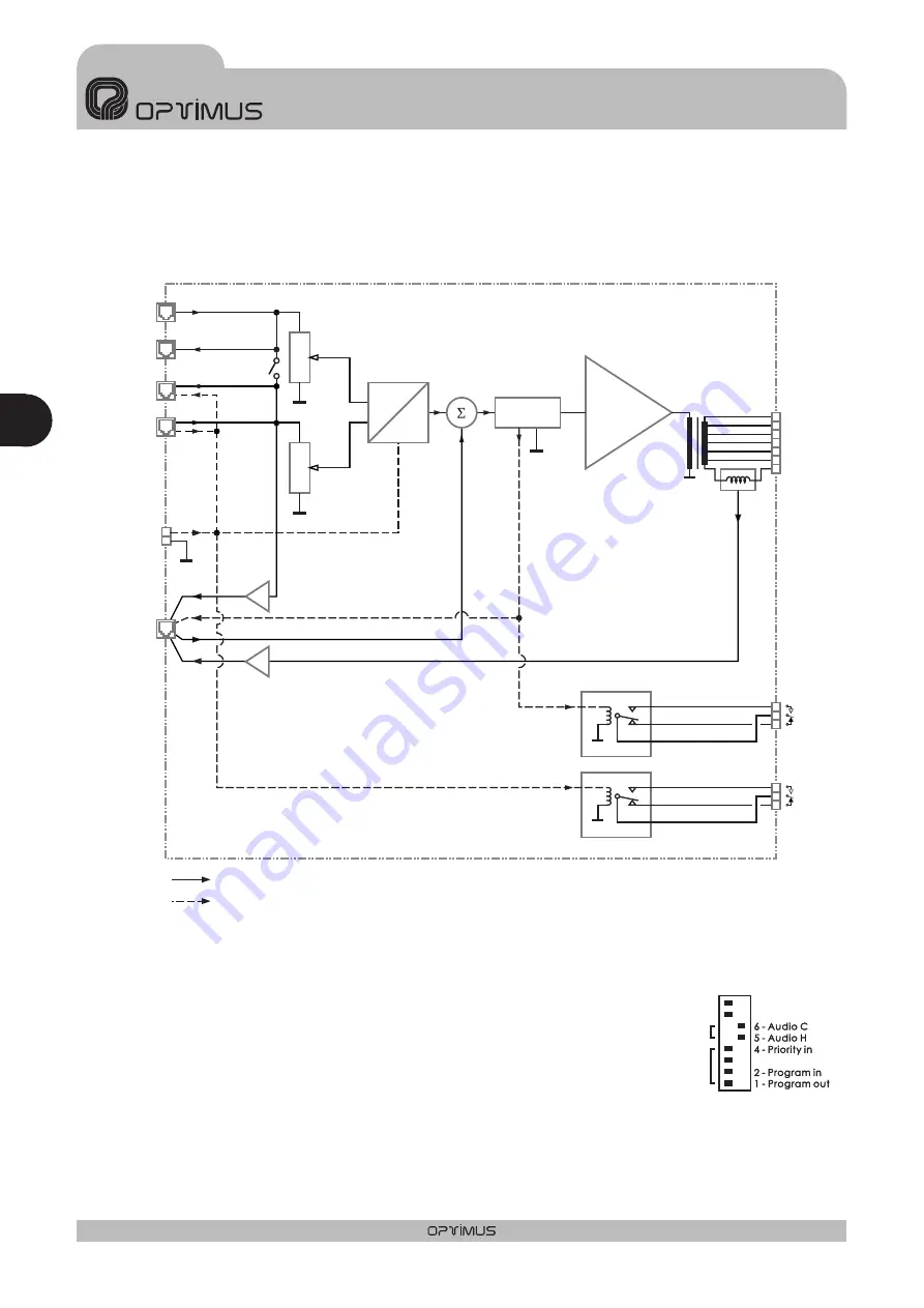
5. DIAGRAMA DE BLOQUES
6. CONFIGURACIÓN DE FÁBRICA
Por defecto, la configuración de fábrica de las etapas de potencia es la
siguiente:
Contacto de prioridad del RJ45 del conector PRIORITY OUTPUT: ON
Contacto de prioridad del RJ45 del conector PRIORITY INPUT: ON
Unión de la señal de los canales PRIORITY y PROGRAM: OFF
Unión de la pantalla del cable y el conector hacia la massa del
amplificador: ON
ON
OFF
PRI-PRO LINK
PRI-PRO LINK
SHIELD-GND
LINK
SHIELD-GND
LINK
7 - Priority ctrl. in
7 - Priority ctrl. in
8 - Priority ctrl. out
8 - Priority ctrl. out
3 - Priority out
3 - Priority out
DIPSWITCH CONFIGURATION
Otras configuraciones
JP1 (puente interno) = OFF
JP2 (puente interno) = ON
Surveillance Shield - Ground Link
E S PA Ñ O L
AMPLIFICADORES UP-366, UP-246, UP-126 y UP-66
Esp
1 0
UP-366, UP-246, UP-126 y UP-66
Versión 1.1


