


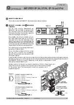


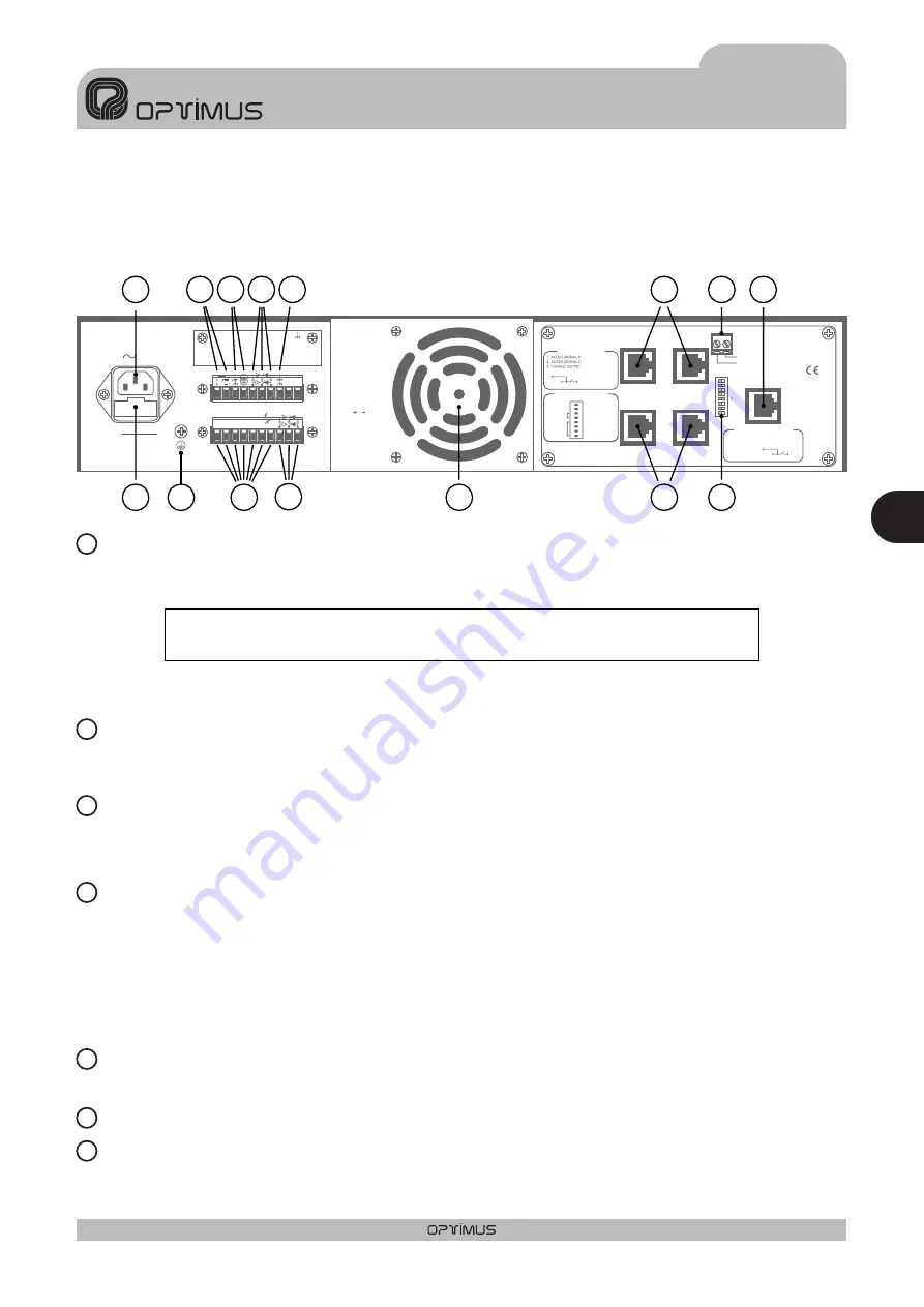
3. REARVIEW
CONNECTIONTO 230V a.c. MAINS SUPPLY
POWER FUSE
BATTERY POWER INPUT
CONNECTION OFTHE SIGNAL MASSTOTHE FRAME
FAIL RELAY
GROUND CONTACT
CHASIS CONTACT
The rear panel incorporates a CEE 22 plug which allows the amplifier to be connected to a mains supply via the
cable supplied.
The power transformer is designed to be able to operate with different voltages. These amplifiers are factory
preset at 230V a.c. but on demand can also be prepared for use with other voltages.
This is contained in the compartment located under the power inlet. This compartment also contains a spare
fuse.
This allows for these amplifiers to be used in safety installations through their connection to a 24V d.c. battery.
The ON/OFF switch does NOT cut off the battery power supply.
In all loudspeaker systems it is very important to have only one connection point between the signal mass and
the power supply ground terminal.
If the loudspeaker assembly is made up of several units, the frames will probably be connected either through
the power supply ground terminal or because they are rack mounted.
If the signals are also connected through the signal circuits, it is advisable to remove the jumpers between the
signal mass and the frame of all the units but one.
It is activated when the protection of the amplifier fails or when the power suplí of the amplifier is off.
Attention: Keep the unit away from water or splatterings of any type
PRIORITY
CTRL. INPUT
GND
PRIORITY
INPUT
PRIORITY
OUTPUT
PROGRAM
INPUT
PROGRAM
OUTPUT
ON
OFF
POWER AMPLIFIER
240W RMS (312W IHF)
U P - 2 4 6
Engineered in EU (Spain)
Made in China
OPTIMUS S.A.
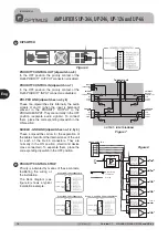
PRI-PRO RJ CONNECTION
6. PRIORITY
8.
METAL
SHIELD
GND
(WHEN BALANCED)
7
8
6
5
3
2
1
DIPSWITCH CONFIGURATION
ON
OFF
PRI-PRO
LINK
SHIELD-GND
LINK
7. Priority ctrl. in
6. Audio C
5. Audio H
4. Priority in
8. Priority ctrl. out
3. Priority out
2. Program in
1. Program out
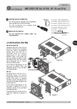
SURVEILLANCE
SURVEILLANCE RJ CONNECTION
1. OSC IN
2. NC
3. OSC OUT 1
4. PROTECT
5. OSC OUT 2
6. PRI OUT
7. +24VDC OUTPUT
8.
METAL
SHIELD
GND
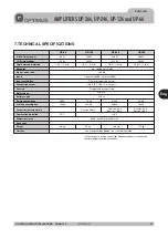
24V
FAIL
O U T P U T S
0
50V 70V 100V
4Ω 8Ω 16Ω
SURETY PAGING
Fuse
O U T P U T S
0
50V
FAIL
SURETY
PAGING
70V 100V
16 Ω
8Ω
4Ω
24V
FAN
POWER
SUPPLY
230V
50/60 Hz
I N P U T / O U T P U T C O N T A C T S
1
2
3
4
5
6
7
8
9
Figure 2
2
1
3
4
5
6
7
15
5
9
4
3
6
12
8
1
13
14
10
2
11
7
Eng
1 5
UP-366, UP-246, UP-126 and UP-66
Version 1.1
E N G L I S H
AMPLIFIERS UP-366, UP-246, UP-126 and UP-66


