


OPTIMUM
M A S C H I N E N - G E R M A N Y
Version 1.0.1 dated 2018-01-31
Page 35
Translation of the original instructions
TM4010 | TM4010D
GB
T
M
4010_
T
M
4010D_G
B_4
.f
m
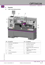
4.3
Switching on the machine
Switch on the main switch.
Switch the control on.
The control lamp for operation must be on.
Check that the emergency-stop button is not pressed or is unlocked. Turn the emergency-
stop push button to the right in order to release the push button.
Close the lathe chuck protection.
4.4
Switching the machine off
If the lathe has been shut off for a longer period of time, switch it off using the main switch
and secure it against being unintentionally switched back on.
CAUTION!
Only press the emergency stop button in a genuine emergency. You should not use the
emergency-stop button to stop the machine during normal operation.
4.5
Resetting an emergency stop condition
Set the rotational direction control lever to the neutral position.
Unlock the emergency stop switch again.
Switch the control on.
4.6
Power failure, Restoring readiness for operation
Set the rotational direction control lever to the neutral position.
Switch the control on.
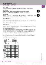
4.7
Momentary switch, direct run
Use the direct run to facilitate engaging the gearbox settings. The spindle starts turning, while
the direct run is activated. The lathe chuck protection must be closed for this. Press the direct
run button only short.
4.8
Speed setting
ATTENTION!
Only change gear positions when the lathe is being completely stopped.
Use the direct run to facilitate engaging the gearbox settings. Adjusting the gear stage takes
place on the headstock.
4.9
Turning direction
The rotational direction of the machine is switched with the shift lever. The lathe can only be
switched on, when the lathe chuck protection is closed.
Move the shift lever down if you want the turning direction to be anti-clockwise.
Move the shift lever up if you want the turning direction to be clockwise.
ATTENTION!
Wait until the lathe has come to a complete halt before changing the rotational direction
with the shift lever.
A change of direction of rotation during operation leads to the destruction of
components.


