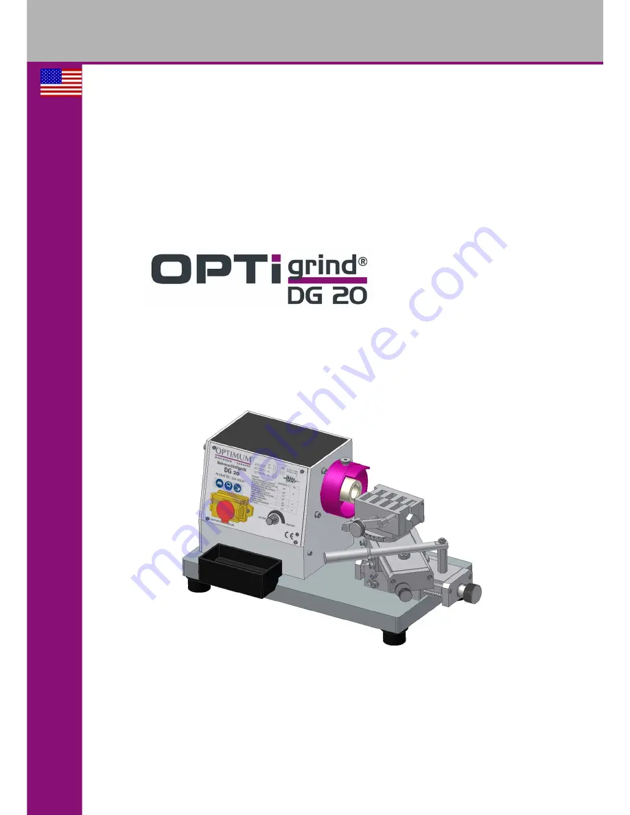
background image

US

OPTIMUM

M A S C H I N E N   -   G E R M A N Y

Item No. 310 0028

Operating manual

Version 1.3.2

Drill bit grinder 

Содержание OptiGrind DG 20

Страница 1: ...US OPTIMUM M A S C H I N E N G E R M A N Y Item No 310 0028 Operating manual Version 1 3 2 Drill bit grinder...

Страница 2: ...12 1 12 Electrical system 12 2 Technical data 2 1 Power Supply 13 2 2 Speed 13 2 3 General 13 2 4 Dimensions 13 2 5 Cup wheel 13 2 6 Working area 13 2 7 Environmental conditions 13 2 8 Emissions 13 2...

Страница 3: ...1 2 Restarting 24 5 2 Inspection and maintenance 25 5 2 1 Replacing the cup wheel 25 5 3 Repair 25 6 Spare parts DG20 6 1 Spare parts 1 of 2 26 6 2 Spare parts 2 of 2 27 6 2 1 Spare parts list 28 6 3...

Страница 4: ...on for its eco nomic operation as well as its long service life In the paragraph Maintenance all maintenance works and functional tests are described which the operator must perform in regular interva...

Страница 5: ...regulations legal regulations for accident prevention the prohibition warning and mandatory signs as well as the warning notes on the drill bit grinder Consult OSHA state and local regulations in ord...

Страница 6: ...r that will cause serious injury or death to personnel WARNING Risk a danger that might cause serious injury or death to personnel CAUTION Danger of unsafe procedure that might cause injury to personn...

Страница 7: ...7 Original operating instructions DG20 US 1 2 2 Other pictograms Warning of automatic start up Disconnect main power Activation forbidden Use ear protection Use protective boots Use protective gloves...

Страница 8: ...alternations to the operating values of the drill bit grinder They could endanger personnel and cause damage to the drill bit grinder 1 4 Possible dangers caused by the drill bit grinder The drill bi...

Страница 9: ...operator must Obligations of the operator train the staff instruct the staff in regular intervals at least once a year on monitoring all safety standards that apply to the machine maintaining the oper...

Страница 10: ...or before using flammable additives e g solvents 1 8 Safety devices Operate the drill bit grinder only with properly functioning safety devices Stop the drill bit grinder immediately if there is a fa...

Страница 11: ...switch is provided with an EMER GENCY STOP function Open the cover of the switch in order to turn the drill bit grinder on Close the cover after turning on in order to guarantee the EMERGENCY STOP fu...

Страница 12: ...re that your work does not endanger anyone Use safety glasses The instructions of this manual must be observed strictly during assembly operation main tenance and repair Do not work on the drill bit g...

Страница 13: ...TION The mentioned numerical value is an emission level and not necessarily a safe working level Unless the degree of noise emission and the degree of noise disturbance are depending on one another it...

Страница 14: ...ng which the operator is exposed to the noise Consult OSHA state and local regulations in order to determine compliance dangers and risks to the operator CAUTION The machine operator has to wear an ap...

Страница 15: ...cides with the maxi mum speed of the drill bit grinder It is further necessary that the maximum grinding speed does not exceed 16 m s 3150 RPM or that the outer diameter of the cup wheel abrasive whee...

Страница 16: ...in a way that possibly used coolant cannot penetrate into the ground Protruding parts such as stops handles etc need to be secured by measures provided by the customer if necessary in order to avoid...

Страница 17: ...safety devices are installed and activated Any problem should be eliminated immediately Stop the drill bit grinder immediately in the event of any problem in operation and make sure it cannot be star...

Страница 18: ...chisel edge more rubbing than cutting requires a reduction of the chisel edge of the bit for ductile steel or other ductile material if large drills are drilling directly into solid material This proc...

Страница 19: ...ter of less than 5 mm 0 2 should jut out of the bit holder with its bit by about 10mm 0 4 Drill with a diameter of more than 5mm should jut out of the bit holder with its bit by about 20 mm 0 8 INFORM...

Страница 20: ...inted angle Inclining the supporting plane The base should be horizontal to the top slide Inclining it to the rear reduces the clearance angle relief produced by grind ing Inclining it to the front en...

Страница 21: ...st the limit stop screw so that if you move the top slide by means of the motion lever the bit holder won t contact the cup wheel but the drill inserts into the cup wheel as much as possible Fig 4 9 A...

Страница 22: ...he pointing procedure when you recognize a regular grinding pattern on the drill INFORMATION Even slightly bent drills cannot be repointed on the drill bit grinder 4 8 Sharpening the cutting edges ATT...

Страница 23: ...completely to the rear Turn the drill in the bit holder as far as the cutting edges of the drill are offset by 45 to the match edges on the bit holder Fig 4 12 Match edge on the bit holder Loosen the...

Страница 24: ...ufactured Installations and equipment of other manufacturers must also be in optimum condition 5 1 Safety WARNING The consequences of incorrect maintenance and repair work may include very serious inj...

Страница 25: ...cup wheel is damaged or shows fractures it must not be used Use an 10 mm open end wrench to hold the cup wheel from turning Unscrew the cup wheel by hand by turn ing it counter clockwise In order to...

Страница 26: ...OPTIMUM M A S C H I N E N G E R M A N Y Spare parts DG20 Version 1 3 2 2015 01 22 26 Original operating instructions DG20 US 6 Spare parts DG20 6 1 Spare parts 1 of 2 Fig 6 1 DG20 1 of 2...

Страница 27: ...OPTIMUM M A S C H I N E N G E R M A N Y Spare parts DG20 Version 1 3 2 2015 01 22 27 Original operating instructions DG20 US 6 2 Spare parts 2 of 2 Fig 6 2 DG20 2 of 2...

Страница 28: ...rew 1 0372013 30 Nut 1 DIN4032 M8 0372059 31 Check plate 3 1 0372021 32 Nut 1 DIN4032 M10 0310002032 33 Feed screw 1 0372018 34 Gib 1 1 0372009 35 Pin 1 A5x10 0310002035 36 Rotary plate 1 0372006 37 H...

Страница 29: ...762 M4x12 0310002081 82 Coolant tray 1 0372039 83 Washer 4 DIN125 8 0310002083 84 Hexagon head cap screw 4 DIN4762 M8x20 0310002084 85 Cushion 4 0372065 86 Line filter 1 0310002086 87 Knob 1 031000208...

Страница 30: ...OPTIMUM M A S C H I N E N G E R M A N Y Spare parts DG20 Version 1 3 2 2015 01 22 30 Original operating instructions DG20 US 6 3 Wiring diagram Fig 6 3 Wiring diagram...

Страница 31: ...ating instructions DG20 US 6 3 1 Spare parts list electrical components Pos Designation Qty Size Item no 1F1 1F2 Fuse 2 031000201F1 LF Line filter 1 03100020LF 1A1 Control board 1 031002073 1R1 Potent...

Страница 32: ...ither partial nor total The company reserves the right to make technical alternations without prior notice 7 2 Terminology Glossary 7 3 RoHS 2002 95 CE The sign on the product or on its packing indica...

Страница 33: ...f any unauthorized recommendations opinions or advice as to the choice installation or use of products Product Suitability Many jurisdictions have codes and regulations governing sales construction in...

Страница 34: ...oltage Directive 2014 35 EC The safety objective meet the requirement of EC Directive 2006 95 EC The following harmonized standards were applied EN 61029 2 4 2011 Safety of transportable motor operate...

Страница 35: ...ns 13 Environmental conditions 13 F First use 16 I Installation and assembly 16 L LIMITED WARRANTY 33 M Maintenance 24 O Obligations User 9 Operation 17 Other pictograms 7 P Power Supply 13 Proper use...

Страница 36: ...OPTIMUM M A S C H I N E N G E R M A N Y Version 1 3 2 dated 2015 01 22 Page 36 Original operating instructions DG20 US...

Отзывы: