background image

Page 11

Only for IS-01SMD

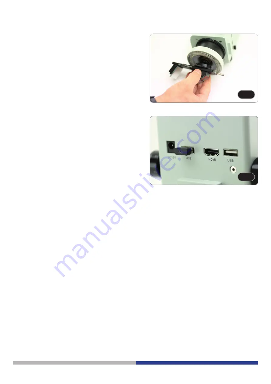
Screw the 3D attachment on the lens thread on the microscope 

body. (Fig. 5)

F

Fig. 5

ig. 5

F

Fig. 6

ig. 6

5. 

Connect the wireless mouse receiver in the USB port 

 , the 

HDMI cable in the port 

 and the power supply jack in the 

connector 

. (Fig. 6)

6. 

Connect a USB flash disk into the port 

.

•  There is no ON-OFF switch on the microscope: when 

the power supply is connected, the system starts up 

automatically and begins projecting images onto the 

monitor.

•  It takes approximately 10-15 seconds for the system to 

start up before the image is displayed.

Содержание INSPECTION SYSTEMS Series

Страница 1: ...Ver 2 1 2021 INSTRUCTION MANUAL INSPECTION SYSTEMS Series Model IS 01 IS 01SMD...

Страница 2: ...ol 18 10 1 2 Image capture 20 a USB flash drive insertion 20 b Image capture operation 20 c Prefix 20 d Image Format 20 e Image Naming Rules 21 10 1 3 Recording 21 10 1 4 Open Image 22 10 1 5 Image co...

Страница 3: ...ty deriving from incorrect instrument use uses that does not comply with this manual 2 Safety Information Avoiding Electrical Shock Before plugging in the power supply make sure that the supplying vol...

Страница 4: ...Page 4 Stand Drop prevention ring Focus system Microscope body Ringlight HDMI cable Power supply Wireless mouse Dust cover 3 Package content 3 1 IS 01...

Страница 5: ...Page 5 Stand Drop prevention ring Focus system Microscope body Ringlight 3D attachment HDMI cable Power supply Wireless mouse Dust cover 3 2 IS 01SMD...

Страница 6: ...glasses Traces of grease or other residuals may deteriorate the final image quality and corrode the optics surface in a short time 5 Intended use Standard models For research and teaching use only Not...

Страница 7: ...Page 7 PILLAR FOCUS KNOB STAND DROP PREVENTION RING WIRELESS MOUSE MICROSCOPE BODY 7 Instrument description 7 1 IS 01 ZOOM KNOB RINGLIGHT LIGHT INTENSITY ADJUSTMENT KNOB...

Страница 8: ...Page 8 7 2 IS 01SMD PILLAR FOCUS KNOB DROP PREVENTION RING WIRELESS MOUSE MICROSCOPE BODY ZOOM KNOB RINGLIGHT 3D ATTACHMENT LIGHT INTENSITY ADJUSTMENT KNOB STAND...

Страница 9: ...Page 9 Back side USB PORT FOR FLASH DRIVE HDMI CABLE CONNECTOR USB PORT FOR MOUSE POWER SUPPLY CONNECTOR...

Страница 10: ...1 2 Insert the focus system in the pillar and lock it with fixing knob Fig 2 3 Insert the microscope body in the hole of the focus system and lock it with the fixing knob Fig 3 4 Align the pins of the...

Страница 11: ...ort the HDMI cable in the port and the power supply jack in the connector Fig 6 6 Connect a USB flash disk into the port There is no ON OFF switch on the microscope when the power supply is connected...

Страница 12: ...e 9 3 Parfocality adjustment 1 Rotate the zoom adjustment ring to the minimum magni fication Fig 9 2 While observing on the monitor focus the specimen 3 Rotate the zoom adjustment ring to the maximum...

Страница 13: ...ion that the standard magnification positions are obtained Only for IS 01SMD By sliding the 3D attachment the system allows a quick switching between Straight view and 3D view Fig 11 Once inserted int...

Страница 14: ...Page 14 10 Use of the software 10 1 Menu Interface a Control...

Страница 15: ...Page 15 b Measurement...

Страница 16: ...orner of the menu to switch the menu display status When Locked always show menu When Unlocked the menu will be hidden shown when the mouse is moved to the top left corner of the monitor c Exposure Ex...

Страница 17: ...Sharp Saturation Ezoom Contrast adjustable value 0 15 Default value 0 Sharp adjustable value 0 15 Default value 4 Saturation adjustable value 0 254 Default value 128 Ezoom adjustable value 1 6 Defaul...

Страница 18: ...rag the crosshair Note Do not press and hold at the intersection of the horizontal and vertical lines Double click a single crosshair to set its color and position center and delete Cross Mark 1 Click...

Страница 19: ...icon of the successful insertion of the USB flash drive is displayed for a few seconds in the upper right corner of the display 3 Now it is possible to take an image b Image capture operation 1 Click...

Страница 20: ...uring recording the icon in the lower right corner of the screen flashes 5 Click on Record icon again 6 The dialog box Capture Stop appears 7 Click OK to stop recording Note The recorded videos are na...

Страница 21: ...Click Full Screen The image interface displays the whole image Click 1 1 The image interface displays part of the picture Press and hold the left mouse button to move the picture position Click Brows...

Страница 22: ...ge Comparison image 5 Click Compare Picture icon Image comparison function closes Note Only images in bmp format are supported for image comparison 10 1 6 Freeze 1 Click Freeze icon 2 The current imag...

Страница 23: ...e of the current 10 1 9 HDR High Dynamic Range HDR adjustable value 0 3 Default value 1 10 1 10 Anti screen Flicker Anti screen flicker effect is achieved after ticking 10 1 11 Black and White Mode Ch...

Страница 24: ...alog box appears In the Line field user can set width and color of the line In the Text field user can set the font size and color of the label b Edge Detection 1 Click Edge Detection icon 2 When sele...

Страница 25: ...create a new template 4 After entering a name in the dialog box click Save icon to save the template Click Delete icon to delete this template Click Edit icon to modify the template Once modification...

Страница 26: ...select the appropriate calibration and unit 1 Select the appropriate tool for measurement when measuring user only needs to click the points of the object to be measured 2 After you click and release...

Страница 27: ...a in the measurement data list with the left mouse button 2 The selected graph data is displayed in shades of gray The color of the selected graph in the image display area becomes the reverse of the...

Страница 28: ...t mouse button to pop up the detailed data dialog box to view all the current detailed measurement data h Mark Tool 1 Click Text icon 2 Draw the position to be marked in the image area enter the comme...

Страница 29: ...the equipment and that the lamp switch is in off position Users should observe all safety regulations of the region The equipment has acquired the CE safety label However users do have full responsibi...

Страница 30: ...t dust on the lenses Clean the lenses The image is not shown on the screen Power supply is unplugged Connect II Mechanical Section Coarse focus knob is hard to turn Tension adjustment ring is too tigh...

Страница 31: ...te The separate collection of this equipment at the end of its lifetime is organized and managed by the producer The user will have to contact the manufacturer and follow the rules that he adopted for...

Страница 32: ...92 info optikamicroscopes com www optikamicroscopes com OPTIKA Spain spain optikamicroscopes com OPTIKA USA usa optikamicroscopes com OPTIKA China china optikamicroscopes com OPTIKA India india optika...

Страница 33: ...Modello IS 01 IS 01SMD Serie INSPECTION SYSTEMS MANUALE DI ISTRUZIONI Ver 2 1 2021...

Страница 34: ...tta USB 51 b Operazioni di cattura immagine 51 c Prefisso 51 d Formato Immagine 51 e Regole di denominazione delle immagini 52 10 1 3 Registrazione 52 10 1 4 Apri Immagine 53 10 1 5 Confronto tra imma...

Страница 35: ...t derivante da un utilizzo dello strumento non indicato nel presente manuale 2 Informazioni sulla sicurezza Per evitare shock elettrici Prima di collegare il cavo di alimentazione alla presa elettrica...

Страница 36: ...36 3 Contenuto della confezione 3 1 IS 01 Stativo Anello prevenzione discesa Sistema di messa a fuoco Corpo del microscopio Illuminatore anulare Cavo HDMI Alimentatore Mouse wireless Copertina antipo...

Страница 37: ...Pagina 37 3 2 IS 01SMD Stativo Anello prevenzione discesa Sistema di messa a fuoco Corpo del microscopio Illuminatore anulare Dispositivo 3D Cavo HDMI Alimentatore Mouse wireless Copertina antipolvere...

Страница 38: ...che come lenti filtri o vetri Tracce di grasso o altri residui possono ridurre la qualit visiva dell immagine finale e corrodere la superficie delle ottiche in breve tempo 5 Utilizzo previsto Modelli...

Страница 39: ...scrizione dello strumento 7 1 IS 01 COLONNA MANOPOLA DI MESSA A FUOCO STATIVO ANELLO DI PREVENZIONE DISCESA MOUSE WIRELESS CORPO MICROSCOPIO MANOPOLA ZOOM ILLUMINATORE ANULARE MANOPOLA REGOLAZIONE INT...

Страница 40: ...40 7 2 IS 01SMD MOUSE WIRELESS DISPOSITIVO 3D STATI COLONNA MANOPOLA DI MESSA A FUOCO ANELLO DI PREVENZIONE DISCESA MANOPOLA ZOOM MANOPOLA REGOLAZIONE INTENSIT LUMINOSA ILLUMINATORE ANULARE CORPO MICR...

Страница 41: ...Pagina 41 Lato posteriore PORTA USB PER CHIAVE USB CONNETTORE CAVO HDMI PORTA USB PER MOUSE CONNETTORE ALIMENTAZIONE...

Страница 42: ...con la manopola di fissaggio Fig 2 3 Inserire il corpo del microscopio nel foro del sistema di messa a fuoco e bloccarlo con la manopola di fissaggio Fig 3 4 Allineare i pin del corpo del microscopio...

Страница 43: ...o HDMI nella porta e lo spinotto dell alimentatore nella porta Fig 6 6 Collegare una chiave USB nella porta Non c un interruttore ON OFF sul microscopio quando l alimentazione collegata il sistema si...

Страница 44: ...andimento Ora la regolazione della parfocalit dovrebbe essere impostata 9 4 Messa a fuoco Mettere il campione da osservare sul piatto del supporto e met tere a fuoco il campione usando le manopole di...

Страница 45: ...tenere un osservazione obliqua dell intero campione 1 Mentre si guarda sul monitor ruotare il dispositivo 3D fino ad ottenere l immagine desiderata 9 5 Variazione dell ingrandimento 1 Ruotare l anello...

Страница 46: ...Pagina 46 10 Uso del software 10 1 Interfaccia del Menu a Controllo...

Страница 47: ...Pagina 47 b Misurazioni...

Страница 48: ...per cambiare lo stato di visualizzazione del menu Quando Chiuso mostra sempre il menu Quando Aperto il menu sar nascosto mostrato quando il mouse viene spostato nell angolo in alto a sinistra del moni...

Страница 49: ...ntrast Sharp Saturation Ezoom Contrast valore regolabile 0 15 Valore di default 0 Sharp valore regolabile 0 15 Valore di default 4 Saturation valore regolabile 0 254 Valore di defaulte 128 Ezoom valor...

Страница 50: ...re il crocefilo Nota non tenere premuto all intersezione delle linee orizzontali e verticali Fare doppio clic su un singolo crocefilo per impostarne il colore e la posizione centrare e cancellare Marc...

Страница 51: ...nserito la chiavetta USB l icona dell avvenuto inserimento della chiavetta USB viene visualizzata per alcuni secondi nell angolo superiore destro del monitor 3 Ora possibile acquisire un immagine b Op...

Страница 52: ...e 4 Durante la registrazione l icona nell angolo in basso a destra dello monitor lampeggia 5 Cliccare nuovamente l icona Record 6 Appare la finestra di dialogo Capture Stop 7 Cliccare OK per interromp...

Страница 53: ...rfaccia immagine visualizza l intera immagine Cliccare su 1 1 L interfaccia immagine visualizza una parte dell immagine Tenere premuto il tasto sinistro del mouse per spostare la posizione dell immagi...

Страница 54: ...liccare sull icona Compare Picture La funzione di confronto delle immagini si chiude Nota solo le immagini in formato bmp sono supportate per il confronto delle immagini 10 1 6 Congela 1 Cliccare sull...

Страница 55: ...HDR valore regolabile 0 3 valore di default 1 10 1 10 Antisfarfallio dello schermo L effetto di eliminazione dello sfarfallio dello schermo si ottiene dopo l abilitazione 10 1 11 Modalit Bianco Nero A...

Страница 56: ...o delle impostazioni Nel campo Line l utente pu impostare la larghezza e il colore della linea Nel campo Text l utente pu impostare la dimensione del carattere e il colore dell etichetta b Rilevazione...

Страница 57: ...er inserito un nome nella finestra di dialogo cliccare sull icona Save per salvare il template Cliccare sull icona Delete per eliminare questo template Cliccare sull icona Edit per modificare questo t...

Страница 58: ...selezionare la calibrazione e l unit appropriate 1 Selezionare lo strumento appropriato per la misurazione quando si misura l utente deve solo cliccare i punti dell oggetto da misurare 2 Dopo aver cl...

Страница 59: ...azione con il tasto sinistro del mouse 2 I dati della grafica selezionata vengono visualizzati in tonalit di grigio Il colore della grafica selezionata nell area di visualizzazione dell immagine diven...

Страница 60: ...finestra di dialogo dei dati dettagliati per visualizzare tutti i dati di misurazione dettagliati correnti h Strumento Segna 1 Cliccare sull icona Text 2 Disegna la posizione da marcare nell area dell...

Страница 61: ...izionato su off Attenersi a tutte le precauzioni di sicurezza della zona in cui ci si trova ad operare L apparecchio omologato secondo le norme di sicurezza CE Gli utenti hanno comunque piena responsa...

Страница 62: ...L immagine non appare sullo schermo I connettori dell alimentatore non sono ben collegati Collegarli II Sezione Meccanica La manopola macrometrica difficile da ruotare L anello di regolazione della te...

Страница 63: ...ne vita organizzata e gestita dal produttore L utente che vorr disfarsi della presente apparecchiatura dovr quindi contattare il produttore e seguire il sistema che questo ha adottato per consentire l...

Страница 64: ...92 info optikamicroscopes com www optikamicroscopes com OPTIKA Spain spain optikamicroscopes com OPTIKA USA usa optikamicroscopes com OPTIKA China china optikamicroscopes com OPTIKA India india optika...

Страница 65: ...Ver 2 1 2021 MANUAL DE INSTRUCCIONES Serie INSPECTION SYSTEMS Modelo IS 01 IS 01SMD...

Страница 66: ...Operaci n de captura de im genes 83 c Prefijo 83 d Formato de la imagen 83 e Reglas de denominaci n de las im genes 84 10 1 3 Grabaci n 84 10 1 4 Abrir la imagen 85 10 1 5 Comparaci n de im genes 86...

Страница 67: ...ellos que utilizan dicho instrumento 2 Informaci n de seguridad Evitar una descarga el ctrica Antes de conectar el microscopio a la toma de corriente asegurarse que la tensi n de entrada del lugar don...

Страница 68: ...gina 68 Soporte Anillo de prevenci n de ca da Sistema de enfoque Cuerpo del microscopio Iluminador anular Cable HDMI Alimentaci n Rat n inal mbrico Cubierta antipolvo 3 Contenido del paquete 3 1 IS 0...

Страница 69: ...P gina 69 Soporte Anillo de prevenci n de ca da Sistema de enfoque Cuerpo del microscopio Iluminador anular Dispositivo 3D Cable HDMI Alimentaci n Rat n inal mbrico Cubierta antipolvo 3 2 IS 01SMD...

Страница 70: ...tros o el cristal Los restos de grasa u otros residuos pueden reducir la calidad visual de la imagen final y corroer la superficie de la ptica en poco tiempo 5 Utilizaci n Modelos est ndar Para uso ex...

Страница 71: ...LAR SOPORTE ANILLO DE PREVENCI N DE CA DA RAT N INAL MBRICO CUERPO DEL MICROSCOPIO 7 Descripci n del instrumento 7 1 IS 01 MANDO AJUSTE DE LA INTENSIDAD DE LA LUZ MANDO DE ENFOQUE MANDO DEL ZOOM ILUMI...

Страница 72: ...72 7 2 IS 01SMD PILAR MANDO DE ENFOQUE ANILLO DE PREVENCI N DE CA DA RAT N INAL MBRICO CUERPO DEL MICROSCOPIO MANDO DEL ZOOM ILUMINADOR ANULAR DISPOSITIVO 3D MANDO AJUSTE DE LA INTENSIDAD DE LA LUZ S...

Страница 73: ...P gina 73 Parte posterior PUERTO USB PARA MEMORIA USB CONECTOR CABLE HDMI PUERTO USB PARA EL RAT N CONECTOR ALIMENTACI N...

Страница 74: ...tema de enfoque en el pilar y bloquearlo con la perilla de fijaci n Fig 2 3 Insertar el cuerpo del microscopio en el orificio del sistema de enfoque y bloquearlo con la perilla de fijaci n Fig 3 4 Ali...

Страница 75: ...erto USB el cable HDMI en el puerto y la toma de alimentaci n en el conector Fig 6 6 Conectar una memoria USB el puerto El microscopio no tiene un interruptor ON OFF cuando se conecta la fuente de ali...

Страница 76: ...que el enfoque sea estable 9 3 Ajuste de la parfocalidad 1 Girar el anillo de ajuste del zoom hasta el m nimo aumen to Fig 9 2 Mientras se observa en el monitor enfocar la muestra 3 Girar el anillo d...

Страница 77: ...n de que se obtienen las posiciones de aumento est ndar S lo para IS 01SMD Al deslizar el accesorio 3D el sistema permite cambiar r pidamente entre la vista recta y la vista 3D Fig 11 Una vez insertad...

Страница 78: ...P gina 78 10 Uso del software 10 1 Interfaz del men a Control...

Страница 79: ...P gina 79 b Medici n...

Страница 80: ...ualizaci n del men Cuando est Bloqueado siempre muestra el men Cuando est Desbloqueado el men se ocultar mostrar cuando el rat n se mueva a la esquina superior izquierda del monitor c Exposici n El aj...

Страница 81: ...arp Saturation Ezoom Contrasto valor ajustable 0 15 Valor por defecto 0 Nitidez valor ajustable 0 15 Valor por defecto 4 Saturaci n valor ajustable 0 254 Valor por defecto 128 Ezoom valor ajustable 1...

Страница 82: ...arrastrar el ret culo Nota No mantener pulsado en la intersecci n de las l neas horizontales y verticales Hacer doble clic en una sola cruz para fijar su color y posici n centrarla y eliminarla Marca...

Страница 83: ...la memoria USB el icono de la inserci n exitosa de la memoria USB se muestra durante unos segundos en la esquina superior derecha de la pantalla 3 Ahora es posible capturar una imagen b Operaci n de...

Страница 84: ...grabaci n 4 Durante la grabaci n el icono de la esquina inferior derecha de la pantalla parpadea 5 Pulsar el icono Record de nuevo 6 Aparece el cuadro de di logo Capture Stop 7 Pulsar OK para detener...

Страница 85: ...imagen muestra la imagen completa Pulsar 1 1 La interfaz de la imagen muestra una parte de la misma Mantener pulsado el bot n izquierdo del rat n para mover la posici n de la imagen Pulsar Browse par...

Страница 86: ...comparaci n 5 Pulsar el icono Compare Picture La funci n de comparaci n de im genes se cierra Nota S lo se admiten im genes en formato bmp para la comparaci n de im genes 10 1 6 Congelar 1 Pulsar el...

Страница 87: ...h Dynamic Range HDR valor 0 3 ajustable Valor por defecto 1 10 1 10 Antiparpadeo de la pantalla El efecto antiparpadeo de la pantalla se consigue tras la marcadura 10 1 11 Modo blanco y negro Marcar p...

Страница 88: ...uraci n En el campo Line el usuario puede establecer el ancho y el color de la l nea En el campo Text el usuario puede establecer el tama o de la letra y el color de la etiqueta b Detecci n de Bordes...

Страница 89: ...u s de introducir un nombre en el cuadro de di logo pulsar el icono Save para guardar el modelo Pulsar el icono Delete para eliminar este modelo Pulsar el icono Edit para modificar el modelo Una vez h...

Страница 90: ...ebe seleccionar primero la calibraci n y la unidad adecuadas 1 Seleccionar la herramienta adecuada para la medici n al medir el usuario s lo necesita pulsar los puntos del objeto a medir 2 Despu s de...

Страница 91: ...n con el bot n izquierdo del rat n 2 Los datos del gr fico seleccionado se muestran en tonos de gris El color del gr fico seleccionado en el rea de visualizaci n de la imagen se convierte en el invers...

Страница 92: ...parezca el cuadro de di logo de datos detallados para ver todos los datos de medici n detallados actuales h Herramienta de Marcado 1 Pulsar el icono Text 2 Dibujar la posici n a marcar en el rea de la...

Страница 93: ...n del microscopio y que el interruptor del iluminador est en la posici n off El usuario debe consultar las normas de seguridad de su pa s El instrumento est dotado de una etiqueta de seguridad CE No o...

Страница 94: ...gen no aparece en la pantalla El enchufe no est conectado al siste ma de iluminaci n Conectar II Secci n Mec nica El mando macrom trico gira con difi cultad El anillo de regulaci n de la tensi n est d...

Страница 95: ...organizada y gestionada por el fabricante Por lo tanto el usuario que desee deshacerse de este equipo debe ponerse en contacto con el fabricante y seguir el sistema que ha adoptado para permitir la r...

Страница 96: ...92 info optikamicroscopes com www optikamicroscopes com OPTIKA Spain spain optikamicroscopes com OPTIKA USA usa optikamicroscopes com OPTIKA China china optikamicroscopes com OPTIKA India india optika...

Страница 97: ...Ver 2 1 2021 MANUEL D UTILISATION S rie INSPECTION SYSTEMS Mod le IS 01 IS 01SMD...

Страница 98: ...l USB 115 b Op ration de capture d image 115 c Pr fixe 115 d Format de l image 115 e R gles de d nomination des images 116 10 1 3 Enregistrement 116 10 1 4 Ouvrir une image 117 10 1 5 Comparaison d im...

Страница 99: ...t instrument Nous d clinons toute responsabilit quant des utilisations de l instrument non conformes au pr sent manuel 2 Pr cautions viter choc lectrique Avant de connecter le c ble d alimentation au...

Страница 100: ...ort Bague de pr vention des chutes Syst me de mise au point Corps du microscope lluminateur annulaire C ble HDMI Alimentation lectrique Souris sans fil Couverture anti poussi re 3 Contenu de l emballa...

Страница 101: ...Page 101 Support Bague de pr vention des chutes Syst me de mise au point Corps du microscope lluminateur annulaire 3D attachment HDMI cable Power supply Wireless mouse Dust cover 3 2 IS 01SMD...

Страница 102: ...ts de l huile de graisse ou d autres r sidus sur les objectifs les filtres les verres diminuent g n ralement la clarit d image 5 Emploi pr vu Mod les standard R serv la recherche et l enseignement Ne...

Страница 103: ...ILIER BOUTON DE MISE AU POINT SUPPORT BAGUE ANTI CHUTE SOURIS SANS FIL CORPS DU MICROSCOPE 7 Description de l instrument 7 1 IS 01 BOUTON DU ZOOM ILLUMINATEUR ANNULAIRE BOUTON DE R GLAGE DE L INTENSIT...

Страница 104: ...104 7 2 IS 01SMD ATTACHEMENT 3D PILIER BOUTON DE MISE AU POINT SUPPORT BAGUE ANTI CHUTE SOURIS SANS FIL CORPS DU MICROSCOPE BOUTON DU ZOOM BOUTON DE R GLAGE DE L INTENSIT LUMINEUSE ILLUMINATEUR ANNUL...

Страница 105: ...Page 105 C t arri re PORT USB POUR CL USB CONNECTEUR DE C BLE HDMI PORT USB POUR SOURIS CONNECTEUR D ALIMENTATION...

Страница 106: ...t dans le pilier et verrouillez le avec le bouton de fixation Fig 2 3 Ins rez le corps du microscope dans le trou du syst me de mise au point et verrouillez le avec le bouton de fixation Fig 3 4 Align...

Страница 107: ...ns le port USB le c ble HDMI dans le port et la prise d alimentation dans le connecteur Fig 6 6 Connectez une cl USB dans le port Il n y a pas d interrupteur ON OFF sur le microscope lorsque l aliment...

Страница 108: ...stable 9 3 Ajustement de la parfocalit 1 Tournez la bague de r glage du zoom jusqu au grossis sement minimum Fig 9 2 Tout en observant sur le moniteur mettez l chantillon au point 3 Tournez la bague d...

Страница 109: ...es positions de grossissement standard sont obtenues Uniquement pou IS 01SMD En faisant glisser l attachement 3D le syst me permet de passer rapidement de la vue droite la vue 3D Fig 11 Une fois ins r...

Страница 110: ...Page 110 10 Utilisation du logiciel 10 1 Interface du menu a Contr le...

Страница 111: ...Page 111 b Mesures...

Страница 112: ...l tat d affichage du menu Lorsqu il est Verrouill il affiche toujours le menu Lorsqu il est D verrouill le menu sera cach affich lorsque la souris sera d plac e vers le coin sup rieur gauche de l cran...

Страница 113: ...harp Saturation Ezoom Contrast valeur r glable de 0 15 Valeur par d faut 0 Sharp valeur r glable de 0 15 Valeur par d faut 4 Saturation valeur r glable de 0 254 Valeur par d faut 128 Ezoom valeur r gl...

Страница 114: ...r ticule Remarque Ne pas appuyer et maintenir l intersection des lignes horizontales et verticales Double Cliquer sur un seul r ticule pour d finir sa couleur et sa position le centrer et le supprime...

Страница 115: ...a cl USB l ic ne de l insertion r ussie de la cl USB s affiche pendant quelques secondes dans le coin sup rieur droit de l cran 3 Il est d sormais possible de prendre une image b Op ration de capture...

Страница 116: ...Pendant l enregistrement l ic ne dans le coin inf rieur droit de l cran clignote 5 Cliquez nouveau sur l ic ne Record 6 La bo te de dialogue Capture Stop appara t 7 Cliquer OK pour arr ter l enregist...

Страница 117: ...een L interface image affiche l image enti re Cliquer 1 1 L interface image affiche une partie de l image Appuyez et maintenez le bouton gauche de la souris pour d placer la position de l image Clique...

Страница 118: ...ence 5 Cliquer sur l ic n Compare Picture La fonction de comparaison d images se ferme Remarque seules les images au format bmp sont prises en charge pour la comparaison d images 10 1 6 Geler 1 Clique...

Страница 119: ...1 9 HDR High Dynamic Range HDR valeur r glable de 0 3 Valeur par d faut 1 10 1 10 Anti scintillement d cran L effet anti scintillement de l cran est obtenu apr s le cochage 10 1 11 Mode Noir et Blanc...

Страница 120: ...s le champ Line l utilisateur peut d finir la largeur et la couleur de la ligne Dans le champ Text l utilisateur peut d finir la taille de la lettre et la couleur de l tiquette b D tection des Bords 1...

Страница 121: ...od le 4 Apr s avoir saisi un nom dans la bo te de dialogue cliquer sur l ic ne Save pour sauver le mod le Cliquer sur l ic ne Delete pour supprimer ce mod le Cliquer sur l ic ne Edit pour modifier le...

Страница 122: ...brage et l unit appropri s 1 S lectionner l outil appropri pour la mesure lors de la mesure l utilisateur doit seulement cliquer sur les points de l objet mesurer 2 Apr s avoir cliqu et rel ch la sour...

Страница 123: ...es de mesure avec le bouton gauche de la souris 2 Les donn es du graphique s lectionn sont affich es en nuances de gris La couleur du graphique s lectionn dans la zone d affichage de l image devient...

Страница 124: ...a bo te de dialogue des donn es d taill es afin de visualiser toutes les donn es de mesure d taill es actuelles h Outil de Marquage 1 Cliquer sur l ic ne Text 2 Dessinez la position marquer dans la zo...

Страница 125: ...e l clairage soit en position arr t L utilisateur devra consulter les normes de s curit s de son pays L appareil incl t une tiquette de s curit C E Dans tous les cas l utilisateur assume toute respon...

Страница 126: ...llon Salet poussi re sur les lentilles Nettoyer les lentilles L image n appara t pas l cran L alimentation lectrique est d bran ch e Brancher le correctement II Section M canique Commande macrom triqu...

Страница 127: ...du pr sent instrument sera effectu e par le fabricant Par cons quent l utilisateur qui souhaite liminer l appareil devra se mettre en contact avec le fabricant et suivre le syst me que celui ci a adop...

Страница 128: ...92 info optikamicroscopes com www optikamicroscopes com OPTIKA Spain spain optikamicroscopes com OPTIKA USA usa optikamicroscopes com OPTIKA China china optikamicroscopes com OPTIKA India india optika...

Страница 129: ...Ver 2 1 2021 BEDIENUNGSANLEITUNG INSPECTION SYSTEMS Series Modell IS 01 IS 01SMD...

Страница 130: ...145 10 1 2 Bildaufnahme 147 a Einsetzen eines USB Sticks 147 b Bildaufnahmevorgang 147 c Pr fix 147 d Bildformat 147 e Regeln f r die Bildbenennung 148 10 1 3 Aufnahme 148 10 1 4 Bild ffnen 149 10 1 5...

Страница 131: ...n Benutzern zur Verf gung stehen Wir lehnen jede Verantwortung f r eine fehlerhafte in dieser Bedienungsanleitung nicht gezeigten Verwendung Ihrer Produkte ab 2 Sicherheitsinformationen Elektrische En...

Страница 132: ...Seite 132 Stand Fallschutzring Fokus System Mikroskopk rper Ringlicht HDMI Kabel Netzteile Kabellose Maus Staubschutzh lle 3 Verpackungsinhalt 3 1 IS 01...

Страница 133: ...Seite 133 Stand Fallschutzring Fokus System Mikroskopk rper Ringlicht 3D Anlage HDMI Kabel Netzteile Kabellose Maus Staubschutzh lle 3 2 IS 01SMD...

Страница 134: ...anderen R ckst nden k nnen die endg ltige Bildqualit t beeintr chtigen und die Optikoberfl che in kurzer Zeit angreifen 5 Verwendung Standardmodelle Nur f r Forschung und Lehre verwenden Nicht f r th...

Страница 135: ...Seite 135 S ULE FOKUSKNOPF STAND FALLSCHUTZRING KABELLOSE MAUS MIKROSKOPK RPER 7 Beschreibung des Instruments 7 1 IS 01 ZOOM KNOPF RINGLICHT EINSTELLKNOPF F R DIE LICHTST RKE...

Страница 136: ...Seite 136 7 2 IS 01SMD 3D ANLAGE STAND S ULE FOKUSKNOPF FALLSCHUTZRING KABELLOSE MAUS MIKROSKOPK RPER ZOOM KNOPF RINGLICHT EINSTELLKNOPF F R DIE LICHTST RKE...

Страница 137: ...Seite 137 R ckseite USB ANSCHLUSS F R USB STICK HDMI KABE LANSCHLUSS USB ANSCHLUSS F R MAUS STROMVERSOR GUNGSSTECKER...

Страница 138: ...en das Fokussystem in die S ule ein und verriegeln es mit dem Befestigungsknopf Fig 2 3 Setzen das Mikroskopk rpers in die ffnung des Fokussystems ein und verriegeln Sie es mit dem Feststellknopf Fig...

Страница 139: ...I Kabel an den Anschluss und die Stromversorgungsbuchse an den Anschluss an Fig 6 6 Schlie en Sie einen USB Stick an den Anschluss an Am Mikroskop gibt es keinen ON OFF Schalter Sobald die Stromversor...

Страница 140: ...ellung der Parfokalit t 1 Drehen den Zoom Einstellring auf die minimale Vergr erung Fig 9 2 Fokussieren das Probe w hrend es auf dem Monitor be obachten 3 Drehen den Zoom Einstellring auf die maximale...

Страница 141: ...dass die Standardvergr erungspositionen erreicht sind Nur f r IS 01SMD Durch Verschieben des 3D Anlage erm glicht das System einen schnellen Wechsel zwischen gerader Ansicht und 3D Ansicht Fig 11 Nac...

Страница 142: ...Seite 142 10 Verwendung der Software 10 1 Men Schnittstelle a Kontrolle...

Страница 143: ...Seite 143 b Messung...

Страница 144: ...en anzeige zu ndern Wenn Gesperrt immer Men anzeigen Wenn Entsperrt wird das Men ein ausgeblendet wenn die Maus in die linke obere Ecke des Monitors bewegt wird c Exposition Die Belichtung kann Auto o...

Страница 145: ...om eingestellt werden Contrast einstellbarer Wert 0 15 Standardwert 0 0 Sharp einstellbarer Wert 0 15 Standardwert 4 Saturation einstellbarer Wert 0 254 Standardwert 128 Ezoom einstellbarer Wert 1 6 S...

Страница 146: ...en Hinweis Dr cken und halten nicht am Schnittpunkt der horizontalen und vertikalen Linien Doppelklicken auf ein einzelnes Fadenkreuz um seine Farbe und Position festzulegen zu zentrieren und zu l sch...

Страница 147: ...B Sticks wird das Symbol f r das erfolgreiche Einstecken des USB Sticks f r einige Sekunden in der oberen rechten Ecke des Displays angezeigt 3 Jetzt ist es m glich ein Bild aufzunehme b Bildaufnahmev...

Страница 148: ...der Aufnahme blinkt das Symbol in der unteren rechten Ecke des Bildschirms 5 Klicken erneut auf das Symbol Record 6 Das Dialogfenster Capture Stop erscheint 7 Klicken auf OK um die Aufnahme zu beende...

Страница 149: ...ll Screen Die Bildschnittstelle zeigt das gesamte Bild an Klicken auf 1 1 Die Bildschnittstelle zeigt einen Teil des Bildes an Halten die linke Maustaste gedr ckt um die Bildposition zu verschieben Kl...

Страница 150: ...eichsbild 5 Klicken auf das Symbol Compare Picture Bildvergleichsfunktion wird geschlossen Hinweis Es werden nur Bilder im bmp Format f r den Bildvergleich unterst tzt 10 1 6 Gefrieren 1 Klicken auf d...

Страница 151: ...uellen Richtung 10 1 9 HDR High Dynamic Range HDR einstellbarer Wert 0 3 Standardwert 1 10 1 10 Anti Bildschirmflimmern Anti Bildschirm Flackereffekt wird nach dem Ticken erreicht 10 1 11 Schwarz Wei...

Страница 152: ...eints Im Feld Line kann der Benutzer Breite und Farbe der Linie einstellen Im Feld Text kann der Benutzer die und die Farbe des Etiketts einstellen b Kantenerkennung 1 Klicken auf das Symbol Edge Dete...

Страница 153: ...n 4 Nach der Eingabe eines Namens im Dialogfeld klicken Save um die Vorlage zu speichern Klicken auf das Symbol Delete um diese Vorlage zu l schen Klicken auf das Symbol Edit um die Vorlage zu ndern N...

Страница 154: ...rechende Kalibrierung und Einheit ausw hlent 1 Auswahl des geeigneten Werkzeugs f r die Messung beim Messen muss der Benutzer nur die Punkte des zu messenden Objekts anklicken 2 Nachdem Sie die Maus a...

Страница 155: ...f die Daten in der Messdatenliste 2 Die ausgew hlten Diagrammdaten werden in Graut nen angezeigt Die Farbe der ausgew hlten Grafik im Bildanzeigebereich wird umgekehrt zur eingestellten Farbe f Grafik...

Страница 156: ...Dialogfeld Detaildaten zu ffnen in dem alle aktuellen detaillierten Messdaten angezeigt werden h Werkzeug markieren 1 Klicken auf das Symbol Text 2 Zeichnen die zu markierende Stelle im Bildbereich ge...

Страница 157: ...e Spannung f r das Mikroskop geeignet ist und dass der Beleuchtungsschalter sich in position OFF befindet Beachten Sie alle Sicherheitsvorschriften des Arbeitsplatzes an dem Sie mit dem Mikroskop arbe...

Страница 158: ...Reinigen die Linsen Das Bild wird nicht auf dem Bildschirm angezeigt Stromversorgungsstecker sind nicht gut angeschlossen Verbinden sie II Mechanischer System Der makrometrische Knopf ist schwer zu dr...

Страница 159: ...ennte Sammlung von Ger ten die am Ende Ihrer Lebensdauer sind wird vom Hersteller organisiert Der Benutzer der dieses Ger t entsorgen m chtet muss dann Kontakt mit dem Hersteller aufnehmen und der Vor...

Страница 160: ...92 info optikamicroscopes com www optikamicroscopes com OPTIKA Spain spain optikamicroscopes com OPTIKA USA usa optikamicroscopes com OPTIKA China china optikamicroscopes com OPTIKA India india optika...

Страница 161: ...Ver 2 1 2021 MANUAL DE INSTRU ES S rie INSPECTION SYSTEMS Modelo IS 01 IS 01SMD...

Страница 162: ...a Inser o de pen drive USB 179 b Opera o de captura de imagem 179 c Prefixo 179 d Formato da imagem 179 e Regras de nomea o de imagens 180 10 1 3 Grava o 180 10 1 4 Abrir imagem 181 10 1 5 Compara o d...

Страница 163: ...e qualquer responsabilidade em caso de Uso do instrumento n o indicada neste manual 2 Informa es sobre a seguran a Para evitar choques el ctricos Antes de ligar o cabo de alimenta o com a tomada el ct...

Страница 164: ...P gina 164 Stand Anel de preven o de quedas Sistema de focagem Corpo do microsc pioy Iluminador anular Cabo HDMI Alimenta o el ctrica Rato sem fios Capa de poeira 3 Conte do da embalagem 3 1 IS 01...

Страница 165: ...P gina 165 Stand Anel de preven o de quedas Sistema de focagem Corpo do microsc pio Iluminador anular Acess rio 3D Cabo HDMI Alimenta o el ctrica Rato sem fios Capa de poeira 3 2 IS 01SMD...

Страница 166: ...gios de graxa ou outros res duos podem deteriorar a qualidade final da imagem e corroer a superf cie ptica em pouco tempo 5 Uso previsto Modelos padr o Apenas para uso em pesquisa e ensino N o se des...

Страница 167: ...a 167 PILAR BOT O DE FOCAGEM STAND ANEL DE PREVEN O DE QUEDAS RATO SEM FIOS CORPO DO MICROSC PIO 7 Descri o do instrumento 7 1 IS 01 BOT O DE ZOOM ILUMINADOR ANULAR BOT O DE AJUSTE DE INTENSIDADE LUMI...

Страница 168: ...P gina 168 7 2 IS 01SMD ACESS RIO 3D STAND PILAR BOT O DE FOCAGEM ANEL DE PREVEN O DE QUEDAS RATO SEM FIOS CORPO DO MICROSC PIO BOT O DE ZOOM ILUMINADOR ANULAR BOT O DE AJUSTE DE INTENSIDADE LUMINOSA...

Страница 169: ...P gina 169 Parte de tr s PORTA USB PARA PEN DRIVE CONECTOR DE CABO HDMI PORTA USB PARA RATO CONECTOR FONTE DE ALIMENTA O...

Страница 170: ...r o sistema de focagem no pilar e bloque lo com o bot o de fixa o Fig 2 3 Inserir o corpo do microsc pio no orif cio do sistema de focagem e bloque lo com o bot o de fixa o Fig 3 4 Alinhar os pinos do...

Страница 171: ...sem fios na porta USB o cabo HDMI na porta e a tomada da fonte de alimenta o no conector Fig 6 6 Ligar um USB flash disk porta N o h interruptor ON OFF no microsc pio quando a alimenta o ligada o sist...

Страница 172: ...mb m tornar a focagem est vel 9 3 Ajuste da parfocalidade 1 Rodar o anel de ajuste de zoom para a amplia o m ni ma Fig 9 2 Enquanto observa no monitor focalize o esp cime 3 Rodar o anel de ajuste de z...

Страница 173: ...ndica o de que as posi es de amplia o padr o s o obtidas Apenas para IS 01SMD Ao deslizar o acess rio 3D o sistema permite uma r pida comuta o entre a vista recta e a vista 3D Fig 11 Uma vez inserido...

Страница 174: ...P gina 174 10 Uso do software 10 1 Interface do menu a Controlo...

Страница 175: ...P gina 175 b Medi o...

Страница 176: ...o do menu para mudar o estado de exibi o do menu Quando Bloqueado mostrar sempre o menu Quando Desbloqueado o menu ser escondido mostrado quando o rato movido para o canto superior esquerdo do monitor...

Страница 177: ...tion Ezoom Contrast valor ajust vel 0 15 Valor por defeito 0 Sharp valor ajust vel 0 15 Valor por defeito 4 Saturation valor ajust vel 0 254 Valor por defeito 128 Ezoom valor ajust vel 1 6 Valor por d...

Страница 178: ...pode arrastar o ret culo Nota N o pressionar e segurar na intersec o das linhas horizontais e verticais Fa a duplo Clicar numa nico reticulo para definir o suo cor e posi o centrar e apagar Reticulo...

Страница 179: ...da pen drive USB o cone da inser o bem sucedida da pen drive USB exibido durante alguns segundos no canto superior direito do monitor 3 Agora poss vel ter uma imagem b Opera o de captura de imagem 1...

Страница 180: ...niciar a grava o 4 Durante a grava o o cone no canto inferior direito do ecr pisca 5 Clicar novamente no cone Record 6 Aparece a caixa de di logo Capture Stop 7 Clicar em OK para parar de gravar Nota...

Страница 181: ...ar Full Screen A interface de imagem mostra a imagem inteira Clicar 1 1 A interface de imagem mostra parte da imagem Manter premido o bot o esquerdo do rato para mover a posi o da image Clicar Browse...

Страница 182: ...comparativa 5 Clicar no cone Compare Picture A fun o de compara o de imagens fecha Nota Apenas imagens em formato bmp s o suportadas para compara o de imagens 10 1 6 Congelar 1 Clicar no cone Freeze...

Страница 183: ...High Dynamic Range HDR valor ajust vel 0 3 Valor por defeito 1 10 1 10 Anti flicker de ecr O efeito de cintila o do ecr alcan ado ap s o fecho 10 1 11 Modo Preto e Branco Marcar para o modo preto e br...

Страница 184: ...ini o No campo Line o utilizador pode definir a largura e a cor da linha No campo Text o utilizador pode definir o tamanho da fonte e a cor da etiqueta b Detec o de bordas 1 Clicar no cone Edge Detect...

Страница 185: ...delo 4 Depois de introduzir um nome na caixa de di logo clicar no cone Save para guardar o modelo Clicar no cone Delete para apagar este modelo Clicar no cone Edit para modificar o modelo Uma vez que...

Страница 186: ...imeiro seleccionar a calibra o e unidade adequadas 1 Seleccionar a ferramenta apropriada para medi o ao medir o utilizador s precisa de clicar nos pontos do objecto a ser medido 2 Depois de clicar e s...

Страница 187: ...de dados de medi o com o bot o esquerdo do rato 2 Os dados gr ficos seleccionados s o apresentados em tons de cinza A cor do gr fico seleccionado na rea de visualiza o da imagem torna se o inverso da...

Страница 188: ...o para abrir a caixa de di logo de dados detalhados para ver todos os dados de medi o detalhados actuais h Ferramenta de Marca 1 Clicar no cone Text 2 Desenhe a posi o a ser marcada na rea de imagem i...

Страница 189: ...steja posicionado no off Seguir todas as precau es de seguran a da zona na qual se trabalha O aparelho aprovado segundo as normas de seguran a CE Os utilizadores t m de qualquer modo plena responsabil...

Страница 190: ...H manchas e p na lentes Limpe a lente A imagem n o mostrada no ecr Conectores de alimenta o n o devi damente ligados Conecte os II Sec o Mec nica O bot o do foco macro est dif cil de rodar O anel de a...

Страница 191: ...dos outros res duos A recolha separada deste equipamento no final da sua vida til organizada e gerida pelo produtor O utilizador ter de contactar o fabricante e seguir as regras que adoptou para a re...

Страница 192: ...optikamicroscopes com OPTIKA USA usa optikamicroscopes com OPTIKA China china optikamicroscopes com OPTIKA India india optikamicroscopes com OPTIKA Central America camerica optikamicroscopes com 100...

Отзывы: