Installation
Important: Please keep the installation procedure below. Improper or no
operation may result if the start-up sequence is not correctly followed.
Step 1
Carefully unpack the contents of the shipping group.
Step 2
Power on the PC(s) and displays.
Step 3
Plug the 12V power adapters to the +12V DC jack on the rear side of
Transmitter and Receiver.
Step 4
IN case of a PC, equipped dual DVI ports
Connect the DVI-1 IN and 2 IN ports of Transmitter to the DVI output
s
of a PC
over two (2) DVI copper cables. Connect upper USB B port of Transmitter to
PC over one (1) USB A-B cable for Keyboard and Mouse. Then, the status
LED (blue) will be turned on
IN case of two PCs, equipped each DVI port
Connect the DVI-1 IN and 2 IN ports of Transmitter to the DVI output of two
(2) PCs over two (2) DVI copper cables. Connect the Transmitter to PCs over
two (2) USB A-B cables for Keyboard and Mouse. Then, the status LED (blue)
will be turned on
If necessary, connect the RS-232 cable, audio, and mic cables to RS-232,
audio IN/OUT, and mic IN/OUT connectors on the front side of Transmitter.
Step 5
Connect the DVI-1 OUT and 2 OUT of Transmitter to the two (2) single-link
DVI displays over DVI copper cables. Attach keyboard and mouse for local
control. You may skip Step 5 if you don
’t need local control.
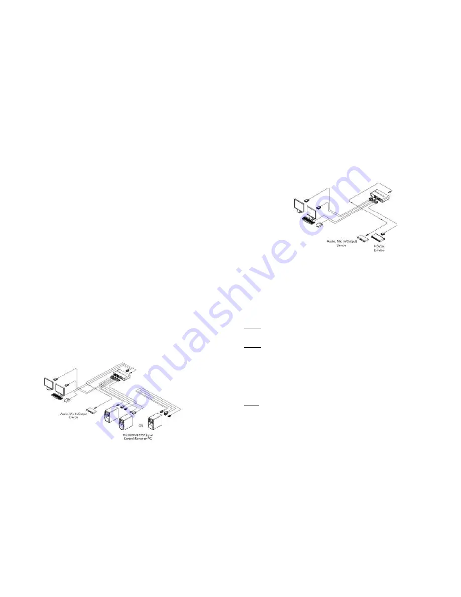
Figure 3
– Connection of Transmitter
1-4 Installation
Step 6
Connect the DVI-1 OUT and 2 OUT port of Receiver to the two (2) single-link DVI
displays over DVI copper cables. Attach keyboard and mouse for remote control. If
necessary, connect the RS-232 cable, audio IN/OUT, and mic IN/OUT connectors
on the front side of Receiver.
Figure 4
– Connection of Receiver
Step 7
Connect one (1) duplex LC fiber to each Optic A port, on the rear side of the
Transmitter and Receiver. Then, the status LED (blue) of Optic A & Video 1 on the
front side of both, will be turned on.
Step 8
Connect another one (1) duplex LC fiber to each Optic B port, on the rear side of the
Transmitter and Receiver. Then, the status LED (blue) of Optic B & Video 2 on the
front side of both will be turned on.
Note1:
each fiber channel shall be connected as Optic A to Optic A and Optic B to
Optic B carefully.
Note2:
1) If PC-1 is turned off or not connected, the status LED (blue) of Optic A &
Video 1 on the front side of them, will be turned off. 2) If PC2 is turned off or not
connected, the status LED (blue) of Optic B & Video 2 on the front side of them will
be turned off.
Step 9
If the connectors are fully engaged, two (2) displays will be shown.
Note3
: KVMX-100-TR reads EDID information of both local side and remote side
displays and then, determines the lowest resolution of them for easy and flexible
installation (Auto-mix EDID programming).
1-5 Installation


