opticis M5-2C2-TR Скачать руководство пользователя страница 4


Step 5  

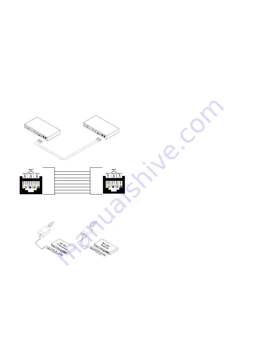
Connect  two(2)  CAT5  or  CAT6  cables. 

But  great  care  should  be  taken 

before connecting cable. Be sure to be connected from A to A port and 
B  to  B  port  as  show  in  Fig.  6,  or  it  will  cause  damage  of  products.

  To 

enhance the transmission quality, Opticis recommend solid shield CAT6 cable 
and be sure to 

use direct type RJ45 connection

 as shown in Fig. 7. 


Figure 6 

– Connection of Two(2) CAT5 Cable 


Figure 7 

– Wiring Diagram of CAT5 Cable (Direct Type)


Step 6 

Connect  an  AC/DC  power  adapter  to  either  Uplink  or  Downlink  module  as 
your availability  of AC  outlet.  You can find  power indication LED  lit on  in  the 
both modules.


Figure 8 

– Connection of AC/DC Power Adapter


1-5 Installation (continued)


             White/Orange             

.


                  Orange                  

.


             White/Green                 

.


                     Blue                     

.


             White/Blue                   

.


                    Green                   

.


            White/Brown                 

.


                    Brown                   

.


M5-2C

2

Transmi

tter

M5-2C

2

Receive

r

Two(2) CAT

5 C

able

s

A B

A B

Step 7 

Power  ON  the  PC  and  display  or  connected  RS-232  devices.  Ensure 
“DVI/HDMI”  and  “LINK”  indication  LEDs  lit  ON,  representing  secure 
connection of all kinds of cables. Confirm LED of the  selected audio  input lit 
ON. 
 

Tip  1:

 If any status LED is not ON normally after all installation as guided in 

the above, we recommend you to push 

“RESET” button while all connections 

are  set  and  the  Uplink  and  Downlink  modules  are  powered  in. 

“Reset” 

function is designed for HPD(Hot Plug Detection) check. 
 

Tip  2:


Avoid  “hot  plugging”  the  Uplink  as  this  is  not  recommended  practice 

with live digital voltages. 


1-6 Installation


Содержание M5-2C2-TR

Страница 1: ...ical Support 1 8 Product Specifications 1 9 Warranty Information 1 10 Regulatory Statements 1 11 Pictorials Figure 1 Overall Digital Video Audio and Serial I O Extender 1 1 Figure 2 Connection of DVI...

Страница 2: ...ion and offers you a cost effective solution for pro A V system Shipping Group of M5 2C2 Digital Video Audio and RS232 Extender Tx and Rx boxes One Uplink module One Downlink module AC DC power adapte...

Страница 3: ...f Downlink Module 1 4 Installation continued Installation Important Please use the installation procedure below Improper or no operation may result if the start up sequence is not correctly followed S...

Страница 4: ...nnection of AC DC Power Adapter 1 5 Installation continued 1 2 3 4 5 6 7 8 White Orange Orange White Green Blue White Blue Green White Brown Brown 1 2 3 4 5 6 7 8 M5 2C2 Transmitter M5 2C2 Receiver Tw...

Страница 5: ...nd others are firmly connected Ensure that power LED lit ON Ensure that the Uplink and Downlink modules connected correctly to the PC and display respectively Check if the PC and display are powered o...

Страница 6: ...the defective item or refund to customer the purchase price paid for the defective product All products that are replaced will become the property of Opticis Replacement products may be new or recond...

Страница 7: ...l interference to radio or television reception which can be determined by turning the equipment off and on the user is encouraged to try to correct the interference by one or more of the following me...

Отзывы: