


Operation Guide
Selection of Control Position
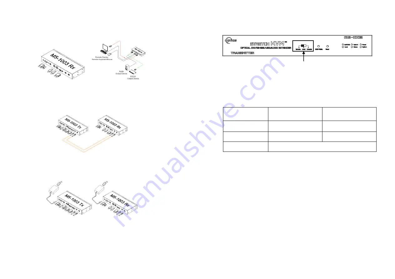
Switch for decision of control position
Figure 7
– Switch for Selecting Control Position
Graphic data is always transmitted to both local DVI out and remote DVI out.
However, USB port for keyboard and mouse is selectable for control at specific
position.
Controllable site is like the table below with the position of switch on the front
panel of transmitter.
The position of
Switch
Local Keyboard/Mouse
(2 USB ports on Tx)
Remote Keyboard/Mouse
(4 USB ports on Rx)
Remote
Disable
Enable
Local
Enable
Disable
Console
Control position is decided by console switch.
Use of Console Switch and Indicator
Console switch and indicator are optionally provided for easy and convenient
control conversion. Connection is like below picture.
Caution
Please DO NOT look directly into the LC receptacles of Uplink module, while
they are powered on, although they are regulated strictly enough to operate
under the Laser Class 1, classified by CDRH/FDA for eye safety.
1-5 Operation Guide
Step 4
Connect the Receiver module to the remote display, keyboard and mouse. If
necessary, connect the RS232 cable and the audio cable to audio output
device and RS-232 device. For proper RS-232 cable type, please refer to Fig
10.
Figure 4
– Connection of DVI cable, keyboard and mouse to Receiver Module
Step 5
Remove dust covers and connect two(2) duplex LC fibers to LC receptacles
of the Transmitter and Receiver modules, as shown in Fig. 5. Ensure the
order of the duplex LC connectors is correct.
Figure 5
– Connection of Two (2) Duplex LC Optical Fibers
Step 6
Connect an AC/DC power adapter to both Transmitter and Receiver modules
as your availability of AC outlets. You can find power indication LED lit on in
the both modules.
Figure 6
– Connection of AC/DC Power Adapter
Step 7
Power ON the PC and display. Power on connected USB, audio and RS-232
devices too. For proper RS-232 cable type, please refer to Fig 10.
Tip 1:
Avoid “hot plugging” the Uplink as this is not recommended practice
with live digital voltages.
1-4 Installation


