OPTICAL SYSTEMS DESIGN
DOC ID: 10104804.doc
OSD840 OPERATOR MANUAL
PAGE 8
1.6
PIN ASSIGNMENTS
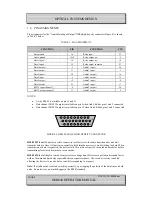
Pin assignments for the “Audio/Data Input/Output” DB26 high-density connector (Figure 2) is shown
in Table 3 below.
TABLE 3: PIN ASSIGNMENT
FUNCTION
PIN
FUNCTION
PIN
Data ground
1,6
Relay input
22
Audio ground
15,18
Relay output n.o.
5
Data1 input +
10
Relay output n.c.
14
Data1 input -
19
Relay output common
23
Data1
2
Audio1 input +
24
Data1 output -
11
Audio1 input -
7
Data2 input +
20
Audio1
16
Data2 input -
3
Audio1 output -
25
Data2
12
Audio2 input +
8
Data2 output -
21
Audio2 input -
17
RS232 input channel 3
4
Audio2
26
RS232 output channel 3
13
Audio2 output -
9
NOTES:
•
2-wire RS485 is available on pins 2 and 11
•
Data channel 1 RS232 output is available on pin 2 when link LK6 has pins 1 and 2 connected
•
Data channel 2 RS232 output is available on pin 12 when link LK4 has pins 1 and 2 connected
FIGURE 2: DB26 FEMALE HIGH DENSITY CONNECTOR
RS485 2-Wire
half duplex is used to connect several devices to the same bus when only one unit
transmits data at a time. All units are normally in high impedance receive mode waiting for data. When
transmission of data is requested, the device waits for a protocol specific turn-around time delay before
transmitting after which it returns to receive mode.
RS485 4-Wire
full duplex is used for master/slave arrangement. Devices are polled and respond faster
with no turn-around time delay required between request/response. The receiver is always enabled
allowing the devices to receive data even while responding to a request.
Note:
If a link doesn't seem to be working correctly, try swapping the polarity of the data lines on both
ends. Some devices are marked opposite the RS485 standard.
1
9
10
19
18
26
Содержание OSD840 SERIES
Страница 1: ...OPERATOR MANUAL OSD840 SERIES DIGITAL VIDEO ETHERNET DATA AND AUDIO FIBER OPTIC TRANSMISSION SYSTEM...
Страница 2: ......
Страница 22: ......
Страница 23: ......


