Page 39
Confidential
– Limited Distribution
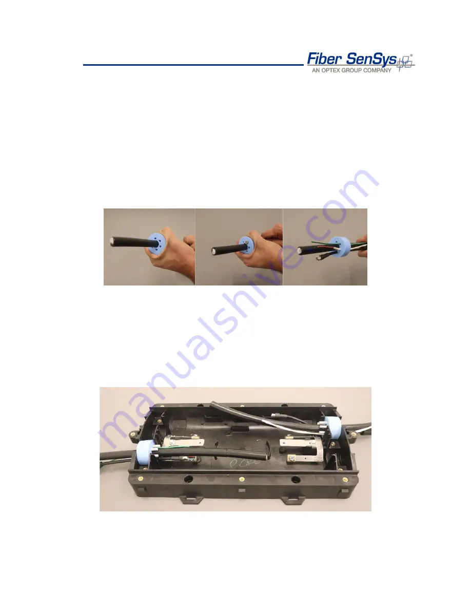
Remove one of the two seven-entry silicon grommets provided in the SUMA kit. Pull the
sensor cable through the large center hole from the outside of the grommet, which does not
have the markings for cable sizing, through to the inside of the grommet, which has sizing
information.
Next, pull the lead-in cable with terminated SMA connector through one of the six smaller
holes in the grommet, it
’s best to place this toward the SUMs female SMA connector side.
Lastly, pull the
≥18AWG 2-conductor power cable and ≥12AWG ground wire, 3.175 mm
(.125 in) or larger cable diameter each, through two of the remaining smaller holes to
provide DC power to the SUM and grounding. Insert grommet plugs in the unused entry
holes.
Figure 37. Inserting the sensor, lead-in, power, and ground cable(s) through the SUMA grommet
Pull a little extra sensor cable through to providing room for the following steps on cable
preparation. The sensor cable, or any of the cables, can be pulled back for fitment when the
SUMs are placed inside the enclosure
.
Step 5
Remove the second of the two seven-entry silicon grommets, and repeat the process from
. This grommet is used for the other side of the sensor cable.
Figure 38. Sensor, lead-in, power, and grounding cables inserted into offset opposite sides of the SUMA


