Only Audio Скачать руководство пользователя страница 3


ENANCER Electrónica S.A.


Page 3 of 9


Rua Max Grundig 9 


4705-820 Braga Portugal                                                                                                                                             [email protected]                                                                
Tel: +351 253 221 484                                                                                                                                                 www.only-smartbuildings.com 


INTRODUCTION  


This document is intended to orientate the work of the installer of the ONLY audio system on the site. The next 
chapters explain how the installation should be made, the precautions to take and the way to test and configure 
the system. 
It is essential to respect it in order to achieve a proper and trouble-free installation.  
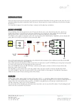
 

AUDIO SYSTEM 

The installation of an audio system is one of the most critical ones. Just a bad connection of a ground, an 
inadequate cable or a bad choice of system architecture may compromise immediately the sound quality. 
Please respect the contents of this manual in order to obtain the desired sound quality.  
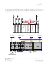
The ONLY audio system comprises audio units, touch panels with OLED display, amplifiers, power supply and 
audio BUS driver with connections to the automation BUS.  


The audio unit receives the 12V power from the D-PS12V15W installed in the switchboard and the audio BUS 
that comes from the feeder D-BUSAUDIO. 
Two audio inputs by 3.5mm jack or RCA connectors can be fixed on an OT-COVER panel, being then connected 
by cable to the inputs IN1 and IN2 existing in the audio unit.  
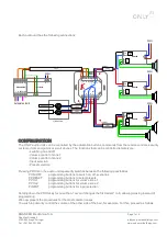
The unit C-FMBT-2Z has local FM RDS tuner, 2 stereo audio inputs, volume control for 2 separate zones, 
Bluetooth, alarm clock and timer.  
The amplifier is connected to the end of the output cable, near the speakers, and it is supplied by 230V~. 
The unit C-FMBT-C has only one zone (OUT1), the output OUT2 is a line output. This output is intended to 
distribute the sound for the remaining parts of the facility. 
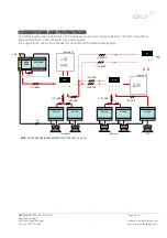
 

CABLES 

All the cables of the audio system must be of the type LIYCY, i.e., shielded cables with a multi-wire shielding.  
In a distributed sound installation, it is required that the power supply and BUS (12V, 0V, B) use a different LIYCI 
cable of the one carrying the audio signals (L, R, GND). Just passing one of them by an external wire or in 
another cable may cause noise in the installation.  
The connection of the shielding to earth must also be carried out on one side of the cable. The shielding should 
not be used as a conductor for the earth. 

230V~


Source 1


Source 2


B-PA08M


B-PA08M


Audio BUS 

Supply


+12,0,BUSA


L,R,0


L,R,0


L,0


R,0


B-PA04S


Содержание Audio

Страница 1: ...Audio Installation Manual ...

Страница 2: ...ww only smartbuildings com Historical Version Date Author Changes 1 0 2010 10 21 1 1 2015 05 14 Minor changes 1 2 2018 09 13 Branding actualization Index Historical 2 Index 2 Introduction 3 Audio System 3 Cables 3 Arquitecture of the Installation 4 Connections and Protections 5 Configuration 7 Measurements and Troubleshooting 9 ...

Страница 3: ...and the audio BUS that comes from the feeder D BUSAUDIO Two audio inputs by 3 5mm jack or RCA connectors can be fixed on an OT COVER panel being then connected by cable to the inputs IN1 and IN2 existing in the audio unit The unit C FMBT 2Z has local FM RDS tuner 2 stereo audio inputs volume control for 2 separate zones Bluetooth alarm clock and timer The amplifier is connected to the end of the o...

Страница 4: ...ry to understand that a sound source e g CD player provides a certain electric current I1 when connected to a sound unit So if we increase the number of audio units connected to the same source we are increasing the current we are asking for at input As the source has a certain impedance R we have a voltage drop V I x R That is if we have 3 audio units we have three times more loss at the source t...

Страница 5: ...chboard The ONLY amplifier is powered by 230V each having its own power supply It is suggested to use a circuit breaker for protection of the whole audio system Bedroom WC Living room NOTE ALL THE RED CABLES SHOULD BE OF THE TYPE LIYCY n X 0 5 mm 12 0 BUSA D PS12V15W L N B 6 A Near the TV Near the TV D BUS AUDIO TV iPod HiFi TV 12 0 BUSA 12 0 BUSA L2 R2 GND L1 R1 GND R2 GND L1 R1 GND 12 0 L N B PA...

Страница 6: ...loor The diagram of the switchboard is as follows Single phase power supply Lighting 1 Lighting 2 Shutters ONLY security central ONLY climatization units ONLY BUS driver D BUSDRV 2 modules D FDRV Wall sockets Cooker Washing Maching 32A 25A 25A 10A 10A 6A 6A 6A 6A 16A 16A 16A 6A Amplifers ONLY Audio BUS driver ONLY D BUSAUDIO 2 modules D PS12V15W ONLY power supply D PS12V15W 5 modules Power supply ...

Страница 7: ...ng buttons to switch on off scenarios P PRESET programming buttons to select presets P VOL1 programming buttons for volume zone 1 P VOL2 programming buttons for volume zone 2 P INPUT programming buttons for input selection Holding down the PROG key for more than 1 second changes the first letter P to E allowing erasing instead of programming We now present the procedures for the most common cases ...

Страница 8: ...e display 4 times 5 Now press the button that you wish to turn up the volume Also in this case the unit switches the unit on and turns up the volume or lowers the volume and switches off completely If you now wish to define a button to select a preset proceed as follows 1 Press PROG repeatedly until P PRESET appears on the display 2 times 2 Now press the button you wish to use to select a preset I...

Страница 9: ...the units must be 12V as is the case for the BUS line If there is a buzz in the sound when the display of the unit is switched on it is because the digital and analogue grounds are connected separate them and the noise disappears Clicks can appear in the sound when a shutter or light is switched on To resolve this situation a filter in the respective circuits should be used Usually an X2 capacitor...

Отзывы: