background image


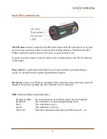
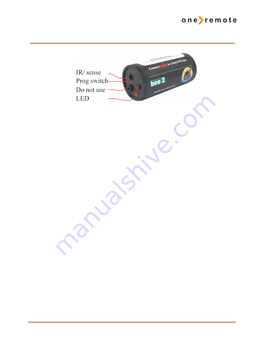
beeLINK2 connections. 


The IR/ sense

 socket is output for the IR-emitter that sends IR to the device to be oper-

ated. In some cases this socket is also used for sensing purposes. Sometimes the Bee-
LINK2 controller needs to know if the device is powered up or not.  

In some cases this socket is used for other serial communications like RS-232 instead 
of IR control. 


Prog switch

 is a push button that must be activated to initiate a programming se-

quence, as described in the option programming chapters. 


Do not use

 socket is for firmware updating of the controller, and connection to special 

adapters. If used for anything else, the controller will be damaged. 


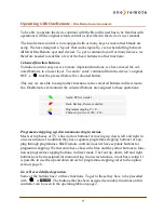
LED

 indicates different operating states: 


Red-green flash: 

No data has been received since power has been applied 


Red flash: 

The controller is in option programming mode. 


Red: 

The controller is active. 


Green: 

The controller is inactive. 


Short off: 

When the controller sends data, the LED turns off 1 sec. 

Содержание BEE2

Страница 1: ...User guide English OneRemote beeLINK2 controller operates Panasonic BlueRay players DMP BD30 BD80 and more User guide type 34016101 BEE2...

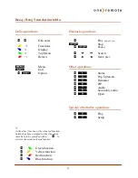
Страница 2: ...ion buttons has been assigned to other functions these have to be preceded with a o to retrieve the actual coloured function oQ Green function oW Yellow function oE Red function oR Blue function o Pla...

Страница 3: ...Beo5 remote controls can be used Beolink 1000 can be used with reduced functionality This guide explains how This beeLINK2 controller is ready for use plug play See the opposite page regarding daily o...

Страница 4: ...beeLINK2 installation page 6 beeLINK2 connections page 8 Operation with OneRemote OneRemote environment page 9 Beolink 1000 page 10 Option programming page 11 Programme zapping option page 11 Menu bu...

Страница 5: ...bus distributes the IR data received with the attached IR receiver from a Beolink 1000 Beo4 or Beo5 to any number of beeLINK controllers It also supplies the attached controllers with power The cable...

Страница 6: ...designed for The IR emitter emits the same IR data as the device s own remote control Emitted IR data is in fact pure light at a frequency just out of the spectrum that the human eye is able to see It...

Страница 7: ...and off via separate commands the beeLINK controller needs to measure the power status of the device This is done using special IR emitters that either measures the status signal on a TV scart output...

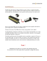
Страница 8: ...is a push button that must be activated to initiate a programming se quence as described in the option programming chapters Do not use socket is for firmware updating of the controller and connection...

Страница 9: ...neRemote environment the coloured buttons are assigned to these operations Programme stepping up down manoeuvring in menus Most set top boxes or TV s has 4 arrow buttons for moving up down left and ri...

Страница 10: ...hen using older remote controls in a beeLINK setup Some buttons on the Beolink 1000 remote controls do actually send the same com mands as differently named buttons on a Beo4 Beo5 Other buttons simply...

Страница 11: ...11 Option programming This controller has no programmable options...

Страница 12: ...e that you might want them to never power off for this reason only The PowerOff option makes you select different ways to power off a device This device has following PowerOff options available Option...

Страница 13: ...LINK2 controller is set to go active on a source button like t d or other source buttons The controller must be programmed to go active on an other source by setting the Active option The beeLINK2 con...

Страница 14: ...ected the controller will go inactive and the LED turn green As a controller goes active it will usually turn on the device if it is not already turned on If the HDMI switch in the example is a beeLIN...

Страница 15: ...15...

Страница 16: ...Made in Denmark by www oneremote dk 34016101u2uk...

Отзывы: