


30
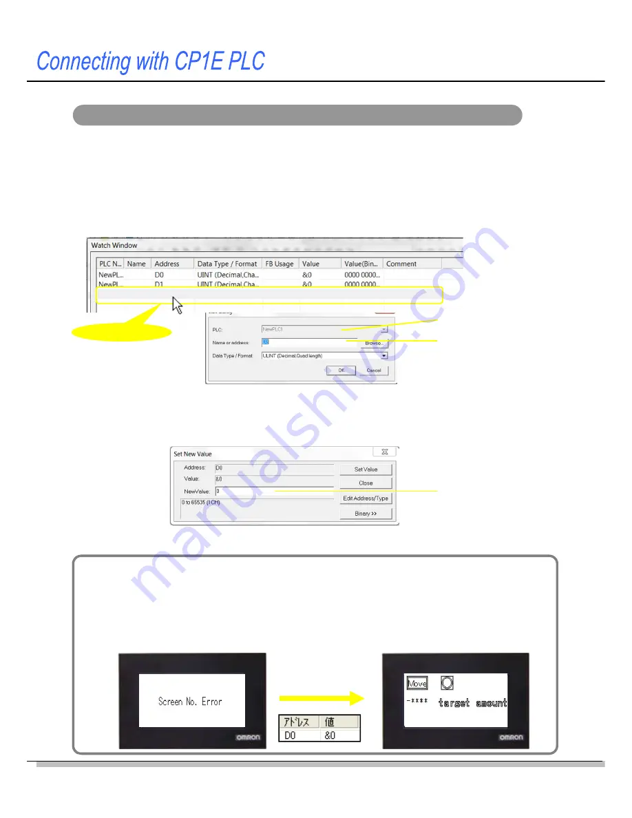
“Screen No. Error” is displayed on the screen
The system memory has an area that is used to switch the NV screen from the PLC. If the
same screen No. stored in the area does not exist in the screen data, the error message
“Screen No. Error” is displayed on the screen.
As for the screen data created in this handbook, the area is allocated to D0 in the PLC.
Write “0” for the base screen 0 to D0 in the CX-Programmer.
Write “0” to D0.
Monitoring or changing the PLC parameters from the CX-Programmer
After connecting the NV and CP1E, confirm NV screen operations. This step is explained
in the next few pages. This subsection explains the Watch Window to monitor and
change the contents of PLC addresses from the CX-Programmer.
< Opening the Watch Window >
Select
View – Window – Watch
from the menu bar,
Double-click!!
Enter an address.
Enter a value.
< Monitoring the parameter values >
Double-click on the
Watch
Window. Enter an address to monitor.
When the PLC is connected online, the present value will be displayed.
< Changing values of addresses >
When the PLC is connected online, double-click on the line of the address in the Watch Window to
change the value.
Enter a hexadecimal value using a prefix of "#". (e.g. #1A)
Enter a decimal value using no prefix or a prefix of "&". (e.g.1234, &1234)
Specify the data type.
* The values cannot be changed when the PLC is in Run mode.
Change the PLC mode to Monitor (program is running) or Program (program is not executed) before changing values.
Содержание NV3Q-MR21
Страница 36: ...2015 0715 0110 V411 E1 02...


