4-1
Section
Components and Their Functions
44
4-1
Components and Their Functions
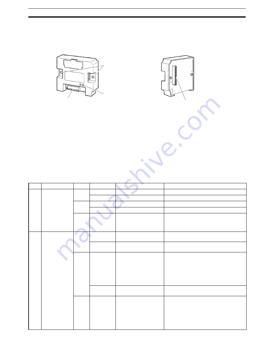
Front view
Rear view
Mounting screws
Attach the DeviceNet In-
terface Unit to the PT.
LED indicators
Indicate the status of the
DeviceNet network and
the I/F Unit.
Communications connector
Connects the Unit to a DeviceNet
network communications cable.
Communications power is also
supplied through this cable.
PT connector
Connects the Unit with the PT.
Note Inspect the DeviceNet Interface Unit for any damage after removing it from its
packaging. Lightly shake the Unit to check whether any parts have broken off
inside.
The following table shows the functions of the LED indicators. The color and sta-
tus of the MS and NS indicators can be used to troubleshoot errors. Refer to 8-2
Troubleshooting with the LED Indicators for more details.
LED
Name
Color
Status
Indicated condition
Meaning
MS
Module status
Green
Lit
Normal status
Normal Unit condition
Flashing
Not set yet
Switch settings are being read.
Red
Lit
Fatal error
Unit hardware error (Watchdog Timer error)
Flashing
Non-fatal error
Minor error such as incorrect switch settings
---
Not lit
No power being supplied
•
Power is not being supplied to Slave Units.
•
Waiting for initialization to start.
•
Unit is being reset.
NS
Network status
Green
Lit
Online, communications
established
Normal network condition (communications
established)
Flashing
Online, communications
not established
Normal network condition but
communications are not established
Red
Lit
Fatal communications
error
Communications error (The Unit detected
an error which makes communications
through the network impossible.)
•
Network power supply error
•
Node number duplication
•
Bus off detected
Flashing
Non-fatal
communications error
Communications timeout
---
Not lit
Offline or power supply
OFF
•
Waiting for completion of the Master’s node
number duplication check
•
Incorrect switch settings (such as an incor-
rect baud rate setting)
•
Faulty network communications cable
•
Power supply OFF
LED Indicators


