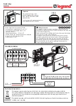
manualshive.com logo in svg
background image

K8AK-TH

6

Operation Method

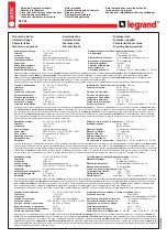
Function Selection DIP Switch

ON

OFF

* Default settings: All OFF

Switch (SW)

Settings

R_SW3

K8AK-TH11S

100°C/°F units (0 to 9)

R_SW2

R_SW1

* Default: 0°C

* Default: All OFF.
* SW8: Not used.

SW

1 2 3 4

K

5 6 7

J

T

E

Pt100

Pt1000

Not used.

Not used.

Upper limit alarm

Lower limit alarm

With latching

Without latching

OFF:


Normally Open

ON:


Normally Closed

Input type

ON

OFF

10°C/°F units (0 to 9)

1°C/°F units (0 to 9)

°

C

EN 61010-1

Safety standards

EMI

EMS

EMC

EN 61326-1

EN 61326-1

* Default: 0°C

* Default: All OFF.
* SW8: Not used.

R_SW3

K8AK-TH12S

R_SW2

R_SW1

SW

1 2 3 4

K

5 6 7

J

T

E

B

R

S

PL

II

Input type

ON

OFF

100°C/°F units (0 to 9)

10°C/°F units (0 to 9)

Upper limit alarm

Lower limit alarm

With latching

Without latching

OFF:


Normally Open

ON:


Normally Closed

Turn OFF the power to the Temperature 
Monitoring Relay before you change the 
switch settings on the side panel. 
The switch settings made on the side panel 
take effect when the power is turned ON.
Use a precision screwdriver to manipulate 
the switches and button.

°

F

°

C

°

F

1,000°C/°F units (0 to 3)

* A temperature setting error 

occurs if this switch is set to a 
value from 4 to 9.

Buy: www.ValinOnline.com | Phone 844-385-3099 | Email: [email protected]

Содержание K8AK-TH

Страница 1: ...or the setting ranges Note When ordering designate the power supply specification Different Relay models are used for 100 to 240 VAC and 24 VAC VDC Refer to Safety Precautions on page 8 For the most r...

Страница 2: ...30 VDC Maximum switching capacity 1 250 VA 150 W Minimum load 5 VDC 10 mA reference values Mechanical life 10 million operations min Electrical life 5 A at 250 VAC or 30 VDC 50 000 operations 3 A at...

Страница 3: ...setting increment 10 C Input K J T E B R S PLII Setting temperature range 3 200 3 100 3 000 2 900 2 800 2 700 2 600 2 500 2 400 2 300 2 200 2 100 2 000 1 900 1 800 1 700 1 600 1 500 1 400 1 300 1 200...

Страница 4: ...ther error Power supply Relay output latched 11 to 14 LATCH_RST or external inputs 4 to 5 Temperature alarm or other error Power supply PWR indicator SV Protect Mode Power supply ALM indicator Tempera...

Страница 5: ...e than one million times If you press and hold the LATCH_RST button for 5 seconds or longer the SV Protect Mode will go into effect When SV Protect Mode is enabled the PWR indicator flashes To disable...

Страница 6: ...ult All OFF SW8 Not used R_SW3 K8AK TH12S R_SW2 R_SW1 SW 1 2 3 4 K 5 6 7 J T E B R S PLII Input type ON OFF 100 C F units 0 to 9 10 C F units 0 to 9 Upper limit alarm Lower limit alarm With latching W...

Страница 7: ...ated The protection function can be released by pressing the output latch reset button on the Temperature Monitoring Relay for at least 5 s or by turning ON the input to the external input terminal fo...

Страница 8: ...he side panel take effect when the power is turned ON If the Temperature Monitoring Relay fails monitoring and alarm outputs may fail to operate This may result in physical damage to the facilities eq...

Страница 9: ...ring Relay to stabilize Take this time into account when you design the control panel 14 Allow at least 30 minutes for the product to warm up During this time the temperature measurements will be inco...

Отзывы: