D41L
16
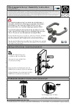
Mounting
For the correct fixing of the safety door switch and the actuator, two
mounting holes for M6 screws are provided
(tightening torque: 6 to 7 N•m).
Any mounting position. The system must only be operated with an
angle of
≤
2° between the safety door switch and the actuator.
The actuator must be permanently fitted to the safety guard and
protected against displacement by suitable measures
(tamperproof screws, gluing, drilling of the screw heads, pinning).
Actuating directions
The diagrams show a closed guard system with a set latching force of 50 N
To avoid any interference inherent to this kind of system and any
reduction of the switching distances, please observe the following
guidelines:
• The presence of metal chips in the vicinity of the safety door switch
is liable to modify the switching distance.
• Keep away from metal chips.
Provide for a sufficient insertion of the actuator into the rotary handle.
Minimum distance between two safety door switches as well as other
systems with same frequency (125 kHz)
The minimum distance from metallic securing surfaces to the face
side "A" and underside "B" of the device is 5 mm.
Accessories for installation (Mounting plate (D41L-MP))
It can be installed by using the following for the type to be installed on
the same side as the door frame.
2°
m
m
5.
3
±
m
m
2
±
2°
Correct
False
A
A
B
B
250
250
[Unit: mm]
250
70
[Unit: mm]