16
•
EN
3
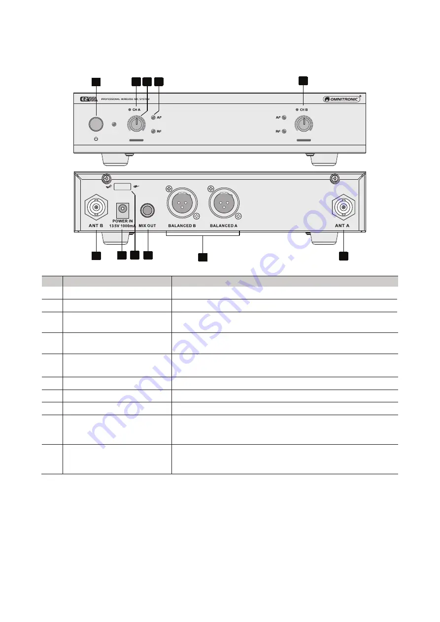
Operating Elements and Connections
3.1 E2 Receiver
No.
Element
Function
1
Receiver channel A
2
Receiver channel B
3
Power switch
Switches the receiver on and off. The adjacent power indicator
lights up when the receiver is powered on.
4
Level controls
Control for the audio signal of the respective channel at the rear
outputs.
5
Status indicators
AF: Lights up when an audio signal from the microphone is received.
RF: Indicates an existing connection to the microphone.
6
Antenna inputs
To connect the antennas provided.
7
Power input
Plug in the connection cable of the supplied power adapter here.
8
Cable grip
For the power cable.
9
Mixed output
Unbalanced 6.3 mm jack for the output of the master signal of all
channels. For connection to a microphone or line input of a mixer
or amplifier.
10
Channel outputs
Balanced XLR outputs for the output signal from the respective
channel. For connection to balanced microphone inputs of a mixer
or amplifier.
3
1
4
5
2
9
7
6
6
10
8


