background image

OIL-HYDRAULIC PRESSES WITH TWO UPRIGHTS

OPERATION AND MAINTENANCE MANUAL

2

INDEX OF TOPICS:

1.

MACHINE ASSEMBLY DRAWING..................................................................................................... 4

2.

TEST CERTIFICATE.......................................................................................................................... 5

2.1

TEST AND INSPECTION DATA (ACCORDING TO SCHLESINGER STANDARDS)........................... 6

3.

EXPECTED USE CONDITIONS .......................................................................................................... 7

3.1

BEFORE OPERATING THE MACHINE ........................................................................................ 7

3.2

DESCRIPTION OF THE MACHINE............................................................................................... 8

3.2.1

ACCESSORIES .................................................................................................................. 9

3.3

MACHINE USE ........................................................................................................................ 10

3.4

RECOMMENDED FLUIDS ........................................................................................................ 11

4.

TRANSPORTATION CONDITIONS.................................................................................................... 12

4.1

EQUIPMENT NECESSARY FOR MONOLITHIC PRESS HANDLING............................................. 12

4.2

PROCEDURE FOR UNLOADING FROM THE MEANS OF TRANSPORT...................................... 13

5.

INSTALLATION CONDITIONS .......................................................................................................... 14

5.1

INSTALLATION OF PRESSES WITH MONOLITHIC STRUCTURE ................................................ 14

5.2

FILLING OF OIL TANK .............................................................................................................. 15

5.3

CONNECTION TO THE ELECTRICAL MAINS SUPPLY ............................................................... 15

5.4

ILLUMINATION OF THE WORK AREA....................................................................................... 16

6.

OPERATION CONDITIONS .............................................................................................................. 17

6.1

ELECTRIC CONTROLS............................................................................................................. 17

6.1.1

MACHINE SETTING CONTROLS ........................................................................................ 17

6.1.2

CONTROL CONSOLE ........................................................................................................ 19

6.2

OIL-HYDRAULIC CONTROLS .................................................................................................... 21

6.3

ELECTRONIC CYCLE CAMS .................................................................................................... 22

6.3.1

CONTROL OF SLIDE STROKE........................................................................................... 22

6.3.2

CONTROL OF THE BLANK HOLDER CUSHION .................................................................. 23

6.4

INDUSTRIAL PC SWITCHING ON PROCEDURE ........................................................................ 24

6.5

PASSWORD ........................................................................................................................... 24

6.6

INDUSTRIAL PC SWITCHING OFF PROCEDURE....................................................................... 24

6.7

DEVICE FOR HOLDING THE SLIDE AT T.D.C. ........................................................................... 25

6.8

KNOCKOUT............................................................................................................................. 25

6.9

FUNCTIONING MODES ............................................................................................................ 26

6.9.1

INITIAL CYCLES................................................................................................................ 26

6.9.2

ADJUSTMENT CYCLE ....................................................................................................... 26

6.9.3

SINGLE CYCLE WITHOUT BLANK HOLDER....................................................................... 26

6.9.4

SINGLE CYCLE WITH INDEPENDENT BLANK HOLDER...................................................... 26

6.9.5

SINGLE CYCLE WITH DIRECT BLANK HOLDER................................................................. 26

6.9.6

BLOCK RESET FOR SLIDE AND CUSHION OVERSTROKE ................................................ 27

6.9.7

SLIDE UPSTROKE CONTROL AFTER B.D.C. STOP............................................................ 27

6.9.8

DIE LOADING ................................................................................................................... 28

6.9.9

DIE UNLOADING............................................................................................................... 29

6.9.10

OPERATION WITH AUTOMATIC FEEDER .......................................................................... 30

6.9.11

AUTOMATIC CYCLE START .............................................................................................. 30

6.9.12

AUTOMATIC CYCLE STOP................................................................................................ 31

Содержание OPI M-400

Страница 1: ...IGHTS OPERATION AND MAINTENANCE MANUAL CUSTOMER MACHINE MODEL SERIAL NUMBER OMERA S r l Via Ponte dei Granatieri 8 36010 Chiuppano VI Italy Tel 39 0445 805444 Fax 39 0445 805404 e mail ucomm omera com...

Страница 2: ...HE WORK AREA 16 6 OPERATION CONDITIONS 17 6 1 ELECTRIC CONTROLS 17 6 1 1 MACHINE SETTING CONTROLS 17 6 1 2 CONTROL CONSOLE 19 6 2 OIL HYDRAULIC CONTROLS 21 6 3 ELECTRONIC CYCLE CAMS 22 6 3 1 CONTROL O...

Страница 3: ...K HOLDER CUSHION CYLINDER 37 7 9 TAKE UP OF SLIDE PLAY 38 7 10 UNIT FOR HOLDING SLIDE AT T D C 39 7 11 MAINTENANCE OF LUBRICATION SYSTEM 39 7 12 ENCODER 40 7 13 TABLE SUMMARIZING MAINTENANCE INTERVENT...

Страница 4: ...OIL HYDRAULIC PRESSES WITH TWO UPRIGHTS OPERATION AND MAINTENANCE MANUAL 4 1 MACHINE ASSEMBLY DRAWING...

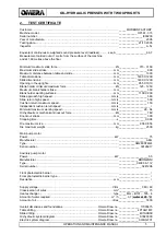
Страница 5: ..._____ 150 Independent cushion return speed mm s _____________________ Minimum maximum working speed mm s ________________ 28 64 Oil hydraulic or mechanical knockout force kN___________________ 160 Kno...

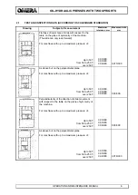
Страница 6: ...T over 250 T 0 03 300 0 05 300 0 08 300 0 015 300 As above but on the perpendicular plane For machines with up to a maximum pressure of Up to 50T from 50 to 250 T over 250 T 0 03 300 0 05 300 0 08 300...

Страница 7: ...e measures taken by the manufacturer of the machine to eliminate sources of safety hazards in the workplace and observes the operation rules HOOK UP MAN The person in charge of handling the machine or...

Страница 8: ...hine top and includes an oil tank variable delivery piston pump with constant power regulator and driven by an electric motor filling and quick exhaust valve with wide port down stroke control blocks...

Страница 9: ...rfacing between the two machines DANGER Even if the machine is prearranged for the connection of one automatic sheet metal feeder as in this case the safety barriers must be modified adapted by the us...

Страница 10: ...limiting devices In the upper part there is a fixed guard which can be controlled as an optional by a safety liming device The 53SA21 selector is used to deactivate the mechanical movable barrier loc...

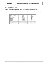
Страница 11: ...SSO NUTO H 46 oil If other lubricants are used check that they have the same characteristics as those described in the comparative oil tables given below Oil type ESSO NUTO H46 Degree of viscosity ISO...

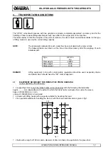
Страница 12: ...al part Type OPI 315 Kg Total weight 29000 Slide weight 3000 Table weight 3100 DANGER Lifting equipment in line with current safety regulations should be used especially chains and cables which should...

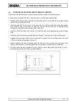
Страница 13: ...hine s parts are not damaged during handling e g oil hydraulic pipes electric cables motors etc position two of the four shims near to the feet 3 so that the press can be straightened by pivoting on t...

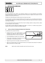
Страница 14: ...riations in voltage which are outside the range allowed by current regulations The area used for manual loading and unloading of the pieces is at the front so sufficient space should be allowed for ma...

Страница 15: ...installation premises is the same as the voltage indicated on the machine test certificate OMERA does not normally supply the general protection device against short circuits and overloading this devi...

Страница 16: ...echnical and work safety standards Particular attention should be paid to the following points supply the lights with low voltage using an isolation transformer protected by fuses carry out the earthi...

Страница 17: ...switches on the auxiliary circuits of the machine The light 51SB2 indicates that the auxiliary circuits supplied with 24V DC are switched on power supply to power relays and auxiliaries STOP AUXILIAR...

Страница 18: ...the machine that require the supervision of the operator to be considered as correctly performed EJECTOR ENABLING key selector 57SB40 when turned towards the right it enables ejector downstroke in th...

Страница 19: ...DANGER The main control pulpit has to be positioned exclusively on the front of the press and has to be used in order to ensure the manual loading and unloading by the main operator The functions of...

Страница 20: ...wn piece at the end of the presswork operation all pieces are punched when turned to the right it controls permanent deactivation of the device which is used to drill the drawn piece at the end of the...

Страница 21: ...ntrol valves and detects the feedback signal from the three analogic pressure switches These are the pressure values which can be set the pressure which determines the slide cylinder working power wit...

Страница 22: ...ters to be set are the following T D C This determines the T D C and that is the slide stopping point during upstroke BRAKING This should be positioned so that the cam intervenes before the die closes...

Страница 23: ...s of counter force of the blank holder cushion during its downstroke this should be numerically higher than the previously set value B D C This determines the cushion B D C this should be numerically...

Страница 24: ...onnel assigned to machine fitting For this purpose two closed envelopes containing the password for accessing reserved areas have been provided with the technical machine documentation One of the enve...

Страница 25: ...nside the slide cylinder The operation of this device is controlled by the INDUSTRIAL PC The main function of this device is to ensure the automatic removal of the drawn piece from the upper part of t...

Страница 26: ...CUSHION UP buttons located on the control console 6 9 3 SINGLE CYCLE WITHOUT BLANK HOLDER This is obtained by turning the relevant switch on the control panel to SINGLE CYCLE de activating the blank...

Страница 27: ...riggered when the slide is at T D C Press the CUSHION DOWNSTROKE buttons located on the control console if the alarm has been triggered when the blank holder is at T D C CAUTION If the intervention of...

Страница 28: ...sure pins just under the work table of the press Clean the upper part of the table and the lower part of the slide carefully using a detergent and a lubricant Position the die on the table of the pres...

Страница 29: ...e INDUSTRIAL PC DANGER Any operation other than the loading unloading of pieces carried out inside the danger zone of the press should only be carried out after the slide safety stop has been operated...

Страница 30: ...from above or behind the press the guards supplied can be de activated using the 53SA20 and 53SA21 selectors to permit the passage of the loading unit from one side and of the drawn piece from the ot...

Страница 31: ...NDUSTRIAL PC located on the hanging push button board of the OPI 315 press and use the AUTOMATIC CYCLE STOP filed relevant to the section consisting of the OPI 315 press and the relevant automatic fee...

Страница 32: ...ulic pumps turn the main switch to position 0 In order to hinder unauthorised manoeuvres of the main switch close the operation handle with a padlock When carrying out maintenance operations which req...

Страница 33: ...of oil is signalled by the INDUSTRIAL PC and by the resulting stopping of the machine the oil level will then need to be topped up 7 2 OIL FILTER The clogging of the oil filter is signalled by the IN...

Страница 34: ...sing 7 4 OIL FILLER CAP Type MP mod TA 80 B10 B001 P01 Omera Code 75702104 Description 1 Strainer 2 Gasket 3 Gasket 4 M5x12 screw 7 5 OIL CHANGE Every 2000 working hours the oil in the circuit should...

Страница 35: ...for the second time turn the CPU key to STOP Keep the CPU key on MRES for one second With the CPU key positioned to STOP insert the new memory card making sure that the black dot is directed upwards T...

Страница 36: ...Up position SHAMBAN STEP SEAL S 55013 3600 A 46 Down position MACMA serie MAD 380360 5 MERKEL serie P6 S1 10 2 H 18 modified according to Omera s drw no 4Z17DD00 6 OR 203 7 Up position SHAMBAN STEP SE...

Страница 37: ...S1 10 2 H 18 modified according to Omera s drw no 4Z17PS00 2 Up position MACMA serie MAD 265240 Down position SHAMBAN STEPSEAL S 55013 2400 A 46 3 GACO OR 81000 NOTE Omera S r l does not supply indivi...

Страница 38: ...5 mm both on the left and right side of the press Progressively tighten screws 5 Progressively tighten the nuts 3 and the screws 1 Check the total play once again Side A adjustment To carry out this o...

Страница 39: ...se may present a danger to operator safety In particular when the micro switch which controls the released slide position is disengaged from the drive cam it should not be possible to activate the dow...

Страница 40: ...king correctly Since the encoders are electronic devices which detect the position of the slide and the blank holder their malfunctioning is immediately evident Maintenance operations should only be c...

Страница 41: ...advised to photocopy the table and scrupulously follow the indications given as comments to each maintenance message see under list Help maintenance alarms MACHINE TYPE _______________________________...

Страница 42: ...OIL HYDRAULIC PRESSES WITH TWO UPRIGHTS OPERATION AND MAINTENANCE MANUAL 42 7 14 COMPARATIVE OIL TABLES...

Страница 43: ...OIL HYDRAULIC PRESSES WITH TWO UPRIGHTS OPERATION AND MAINTENANCE MANUAL 43 7 15 WIRING DIAGRAM...

Страница 44: ...OIL HYDRAULIC PRESSES WITH TWO UPRIGHTS OPERATION AND MAINTENANCE MANUAL 44 7 16 OIL HYDRAULIC DIAGRAM...

Страница 45: ...OIL HYDRAULIC PRESSES WITH TWO UPRIGHTS OPERATION AND MAINTENANCE MANUAL 45 7 17 PNEUMATIC DIAGRAM...

Страница 46: ...OIL HYDRAULIC PRESSES WITH TWO UPRIGHTS OPERATION AND MAINTENANCE MANUAL 46 7 18 LUBRICATION SYSTEM DIAGRAM...

Страница 47: ...OIL HYDRAULIC PRESSES WITH TWO UPRIGHTS OPERATION AND MAINTENANCE MANUAL 47 7 19 TABLE DRAWING...

Страница 48: ...OIL HYDRAULIC PRESSES WITH TWO UPRIGHTS OPERATION AND MAINTENANCE MANUAL 48 7 20 SLIDE DRAWING...

Страница 49: ...OIL HYDRAULIC PRESSES WITH TWO UPRIGHTS OPERATION AND MAINTENANCE MANUAL 49 7 21 KNOCKOUT DRAWING...

Страница 50: ...OIL HYDRAULIC PRESSES WITH TWO UPRIGHTS OPERATION AND MAINTENANCE MANUAL 50 7 22 OTHER DRAWINGS...

Отзывы: