INSTALL GUIDE
GUIDE ID: CST_HA7_G6_G5_20210414
Page 2 of 18
MODEL: OL-HRN-RS-HA7
C
D
A
B
I
F
G
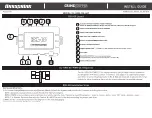
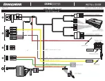
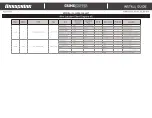
RSX-G5 Layout
J
WHITE 2 PIN LED PORT
F
BLACK 3 PIN ANTENNA PORT
I
BLACK DATA PORTS
-
For Vehicle Interface Module.
(Fortin & iDatalink protocols supported on both ports - see feature #5)
A
BLACK 6 PIN HIGH CURRENT POWER HARNESS
NOTE: OL-HRN-RS-PWR-CST Adaptor Not Included With T-Harness & Will Be Required
B
WHITE 12 PIN MAIN INPUT/OUTPUT HARNESS
C
WHITE 3 PIN DOOR LOCK PORT
H
NOT USED
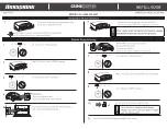
RSX-G5 Installation Steps
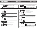
INSTALLATION STEPS:
1) Go to www.OmegaWeblink.com or use WebLink Mobile to fl ash the bypass module with the fi rmware matching the vehicle.
NOTE: iDatalink 2-way protocol is recommended for full functionality.
NOTE: If OEM remote is being used to activate the remote start be sure “Factory keyless RS sequence” is set to “Lock + Lock + Lock” OR “Lock + Lock”
NOTE: For Manual Transmission vehicles Feature #11 MUST be set to the desired setting for proper operation.
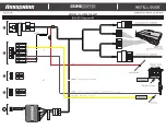
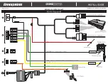
2) Make all the connections shown in the diagram on the following pages.
3) Connect any optional hardware as needed.
4) Select Data Mode and program the bypass module to the vehicle (see module programming instructions).
5) Test the system for all desired functions.
NOTE:
Any features NOT supported by the interface module must be hard wired from the remote start to the vehicle. Refer to the remote start install guide and vehicle wiring
info at www.wiresheet.com (only available for authorized dealers) for instructions.
G
SMART PHONE PORT -
For LINKR-LT or TELE-CONNECT Smart Phone Interface modules
D
RED 3 PIN LOW CURRENT AUX PORT
E
BLUE 2 PIN PROGRAMMING/VALET PORT
E
H
J
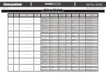
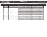
OL-HRN-RS-PWR-CST Required
The OL-HRN-RS-PWR-CST re-confi gures the 6-pin (A) High Current Outputs to
be compatible with the Excalibur T-Harness. This adaptor is required for proper
operation. In some instances features #4 & #26 will need set to options other than
default. In those situations there will be a note indicated the needed settings.
OL-HRN-RS-PWR-CST
RSX-G5-
start

