manualshive.com logo in svg
background image


Page 14


Example #2: Use of the LOW SCALE Parameter 

Setup for a 4-20ma transducer signal corresponding to 500-2000 degrees Fahrenheit temperature i.e. 500 degrees at 4ma 
and 2000 degrees at 20ma (one degree resolution): 
 
   DECIMAL 

POINT 

 = 

9999 

   HIGH 

SCALE 

  = 

2000 

   LOW 

SCALE 

  = 

500 

   OFFSET   = 

4.00 

   TARE 

   = 

0.000 


Example #3: Use of the TARE Parameter 

Setup for a 0-5Vdc transducer signal corresponding to 0-10.00 pounds of material being packaged in a box weighing 0.50 
pounds with display reading in 0.01 lb. increments.  DSP3200 should display the weight of  the material only (not the box 
as well): 
 
   DECIMAL 

POINT 

 = 

99.99 

   HIGH 

SCALE 

  = 

10.00 

   LOW 

SCALE 

  = 

00.00 

   OFFSET   = 

0.00 


TARE   


= 0.50 


SYSTEM CONFIGURATION 

 
After entering the correct pass-code and selecting the blinking 

'SYS'

 (ref. SETUP section), DPS3000 Series goes into 

SYSTEM CONFIGURATION mode.  This mode allows setting up parameters that affect all the channels or the 
instrument in general. 


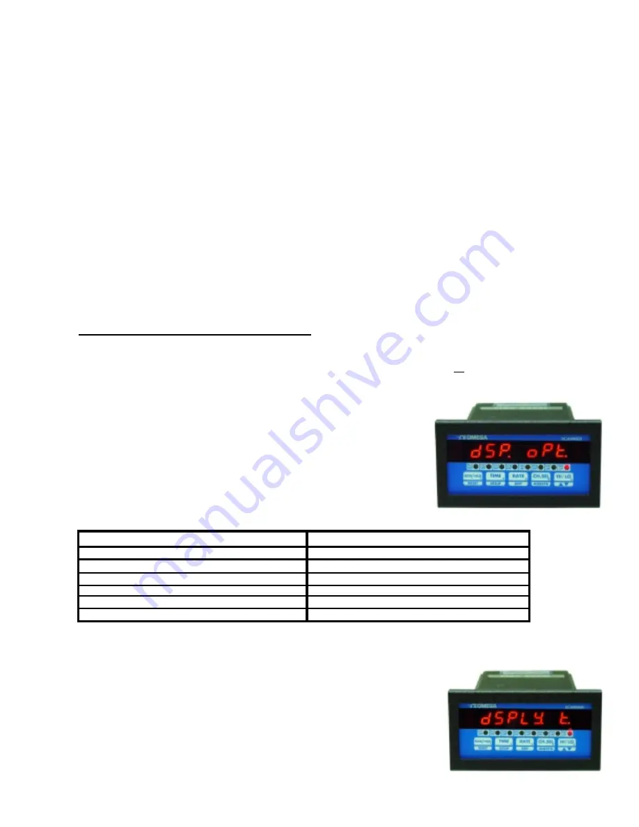
Setup For Display Options 

 
After pushing 

SETUP

 key while 

SYS

 is blinking, the display briefly shows 

'dSP  OPt' 

 (for display option) and then the present Display Option setting.  

Table 3 below lists all 6 display options available. Use 

^v

 key to step thru the 

options. Once the desired Display Option is shown, push 

SETUP

 key to enter 

the setting and go to Setup For Display Time. 


Table 3.  Display Options 


DISPLAY OPTION


DISPLAY WINDOW READS


  1) Display elapsed time   


 ELPSEd 

t


  2) Scan active channels   


 SCAn


  3) Display channel with highest reading 


HI  CHAN


  4) Display channel with lowest reading 


LO  CHAN


  5) Display deviation from SETPOINT 


dSP  dEN


  6) Display channel differential 


CH1 dIF


The channel numbers in Display Option #6 start with 

'CH1  dIF'

 and go up to 

'CH7  dIF'

 (

CH4  dIF

 for 4 channel units). 

Following this the display jumps back to Option #1  (elapsed time), and the cycle is repeated. 
 

Setup For Display Time 

 
The next parameter to be set is DISPLAY TIME.  This determines the number of 
seconds a channel's reading is displayed before moving to the next channel. The 
display will first show 

'dSPLy  t'

  (for Display Time), and then the current setting 

in seconds.  Use  

^v

 key (ref. Setup For High Scale) to set the desired DISPLAY 

TIME.  Once the desired DISPLAY TIME value is displayed, push 

SETUP

 key to 

enter that value and go to setup Relay as Latching or Non-Latching. 


Содержание DPS3100 series

Страница 1: ...http www omega com e mail info omega com Omega com Omega com Omega com Omega comTM TM TM TM DPS3100 DPS3200 series Programmable Scanners...

Страница 2: ...Setup For Engineering Units 13 Setup for Thermocouple Thermistor RTD Inputs 13 Turning Channels ON OFF 13 Temperature units 13 Setup Examples 13 Example 1 Use of the OFFSET Parameter 13 Example 2 Use...

Страница 3: ...F INSTRUMENT 21 POWER 21 OUTPUT CONNECTOR PIN ASSIGNMENT 22 Table 1 DPS3000 Series Output Connector Pin Assignments 22 TROUBLE SHOOTING 23 Factory Channel settings 23 Factory default settings for volt...

Страница 4: ...igit height Over range indication HELP Display test Briefly displays 8 8 8 8 8 8 8 on power up Seven digit display SCALE OFFSET Scale programmable from 1 30000 units Offset programmable from 0 99 99 M...

Страница 5: ...up check for proper power connections before powering up the unit will first display 8 8 8 8 8 8 8 as a display test and then the software revision number The format is rEn x xx where x xx is the revi...

Страница 6: ...hannel whose rate is desired push CH SEL key b Push RATE key once 4 Channel deviation a Select desired channel by pushing CH SEL key b Push RATE DIFF key twice 1st push displays rate 2nd push deviatio...

Страница 7: ...ragraphs give a detailed description and operation of various modes Elapsed Time Mode DPS3000 Series can be programmed to run as timer In this mode the unit will indicate elapsed time in hours minutes...

Страница 8: ...lue On push of a key the channel number and the value of process variable can be displayed Also during SYS Setup the unit can be programmed so that instead of scanning all the channels it will only di...

Страница 9: ...w seconds e g CH1 CH2 for displaying difference between channel 1 and channel 2 If the unit is not programmed for difference mode the differential between any two of the seven channels can be briefly...

Страница 10: ...12 Relay Normally Open Closed 13 Display Units For more details refer to the CHANNEL CONFIGURATION section Three attempts at entering correct pass code are allowed HELP shows up in the display window...

Страница 11: ...will not spend any time scanning it This will also prevent the unit from displaying a HELP message on a channel that has nothing hooked up to it Use v key to select the desired setting If a channel is...

Страница 12: ...the 0 130Vdc correspond to a display of 0 set OFFSET 0 130 NOTE If the input type is CURRENT the Offset value is entered in milliamps If the input type is VOLTAGE the Offset value is entered in milliv...

Страница 13: ...to enter that value and go on to setup Deadband Setup For Deadband After setting a channel s LIMIT the next parameter to be set is channel s relay DEADBAND This parameter is used for eliminating rela...

Страница 14: ...ke the other inputs any alternate units may be programmed for thermocouples The display will first show Cx UNIt x channel after which the current UNITS will be displayed Use v key ref Setup For High S...

Страница 15: ...lay option and then the present Display Option setting Table 3 below lists all 6 display options available Use v key to step thru the options Once the desired Display Option is shown push SETUP key to...

Страница 16: ...p For Cold Junction Calibration After setting Relay Latch Non Latch the next parameter is the cold junction reference temperature The display will first show COLd JN and then the cold junction tempera...

Страница 17: ...e calibration for all channels Also only one type of thermocouple input needs to be calibrated i e J K T or E For example if the calibration is done for a type K thermocouple types J T and E are autom...

Страница 18: ...isplay will indicate LO P for Low Peak before showing the value If an attempt is made to display the high or low peak of a channel which has been turned off in CH Setup the display will read CHx OFF x...

Страница 19: ...ANGE VOLTAGE CURRENT J T C CR AL T C K T T C E T C LO VOLTAGE HI VOLTAGE CURRENT VOLTAGE CURRENT RTD 385 RTD 392 VOLTAGE CURRENT R T C S T C B T C VOLTAGE CURRENT THERMISTOR TC Option TH Option P Opti...

Страница 20: ...ANGE CURRENT RANGE J T C CR AL T C K T T C E T C LO VOLTAGE VOLTAGE CURRENT RTD 385 RTD 392 R T C S T C B T C THERMISTOR TC Option TH Option MV V or C Option Not Selectable RTD Option R S or B Option...

Страница 21: ...ctor outputs or electro mechanical relays Check model number printed on the unit Open Collector Option Whenever a limit is reached an open collector output provides a 5 Vdc signal at 50ma on the outpu...

Страница 22: ...e made to the three terminal connector as shown in figure 3 Also make note that it is very important that the power line inputs and the power ground are not switched Doing so will permanently damage t...

Страница 23: ...Channel 3 Limit Normally Open Closed Negative Output 7 Channel 4 Limit Common Positive Output 8 Channel 4Limit Normally Open Closed Negative Output 9 Channel 5 Limit Common Positive Output 10 Channel...

Страница 24: ...GES AND SOLUTIONS ERROR MESSAGES AND SOLUTIONS ERROR MESSAGE ERROR CONDITION SOLUTION EE EROR The unit was unable to If the message keeps coming up save programmed value unplug the unit and reapply po...

Страница 25: ...e the nuts from the mounting screws on the Panel Meter 3 Insert panel meter into the hole until it is flush with the panel 4 Install the nuts and tighten them till the unit is held firmly against the...

Страница 26: ...Page 25 WARRANTY For Warranty information check Omega s web site at http www omega com...

Страница 27: ...Page 26...

Страница 28: ...Page 27...

Страница 29: ...Page 28...

Отзывы: