


Page - 9
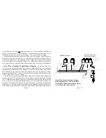
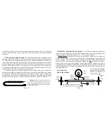
Release
Switch
Release
Solenoid
To 12 Volt
Positive
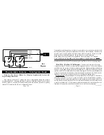
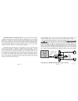
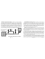
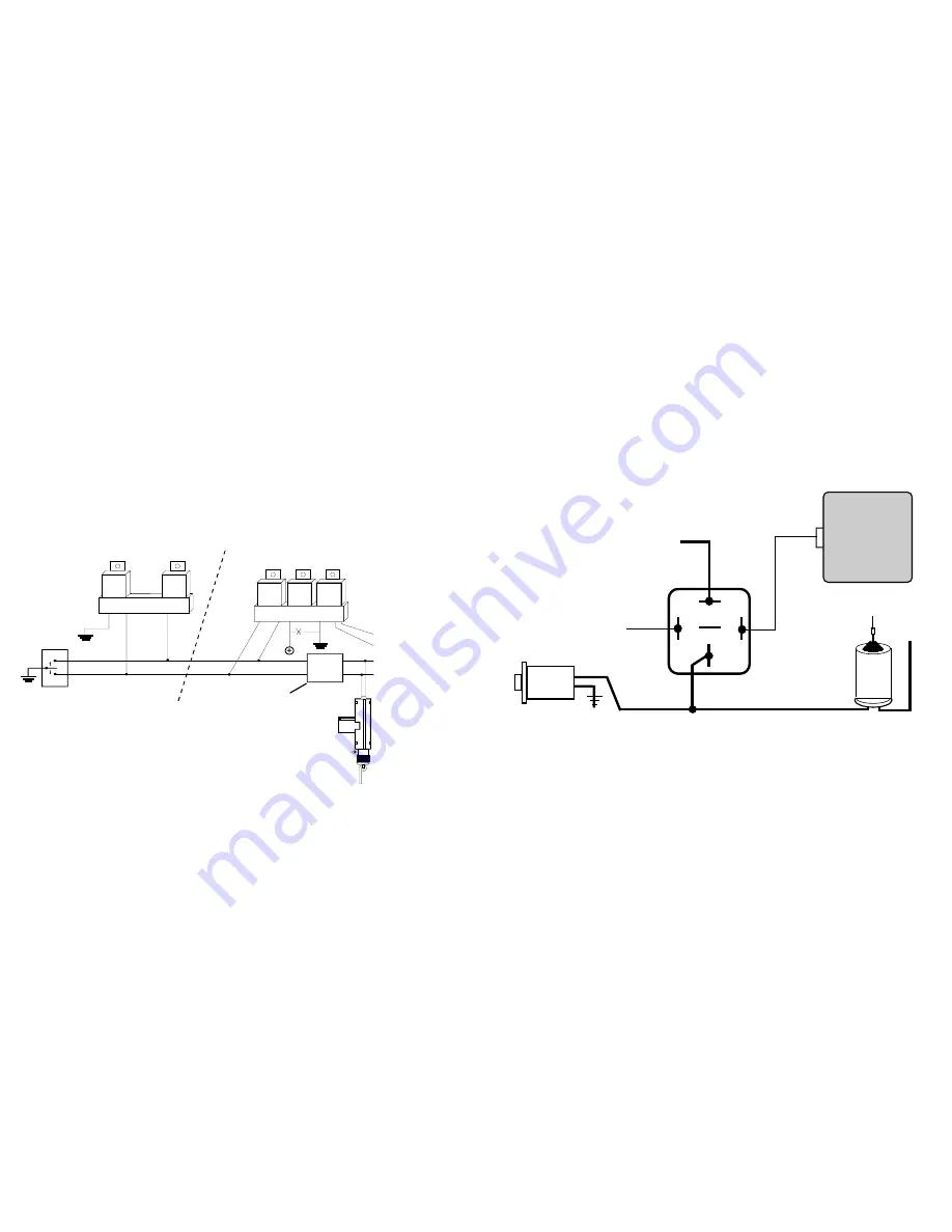
to optional relay pin (85), and connect Constant Positive 12 Volts to relay pin (86). Con-
nect pins 87, 87a & 30 as indicated in the following typical diagram:
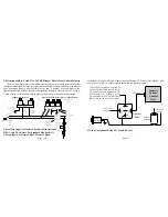
Security
System
Control
Unit
To 12 Volt
Positive
To Positive Or Negative As Needed. In
This Case, Negative Is Required. In Oth-
ers, Positive. In Some Applications The
Wire Will Rest At Ground. Cut The
Wire, Switch Side To Pin 87a, Solenoid
Side To Pin 30 and 12 Volts To Pin 87.
Gray Wire
Optional
Relay
87
30
86 87a 85
Wiring An Optional Relay For Trunk Release.
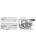
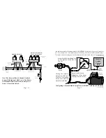
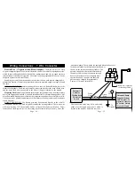
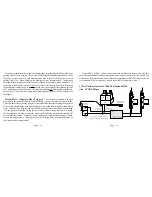
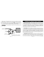
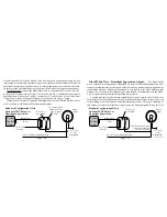
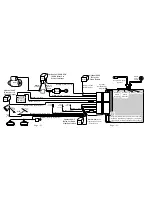
The Optional DLS -3 And 2 Or 3 SPDT Relays - Driver Door Unlock Priority
The DLS-3 is a triple relay socket (three relays are also needed) and is the most universal
interface which allows the security system to lock the vehicle's doors, unlock only the driver's
upon disarming (driver's door unlock priority) and, if desired, a second press of the
transmitter's button within 5 seconds of disarming will unlock all of the doors. The DLS-
3 used with two relays can be used in place of the DLS to lock and unlock all doors.
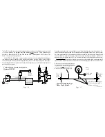
Relay
DLS-3
Relay
Relay
Driver's Doorlock
Actuator
Blue
Brown
Doorlock
Actuators
Violet
Unlock
Lock
CUT HERE
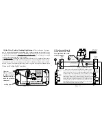
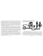
Relay
Relay
Gray
Green
Door
Lock
Switch
Ground
DLS-3 Violet
Wire To
Ground
DLS-3
Blue Wire
To Door
Unlock
Wire.
DLS-3
Green
Wire To
Door Lock
Wire.
Vehicle's
Doorlock
Relay Control
Unit
DLS-3
Pink
Doorlocks With Driver Door Unlock Priority
Standard Doorlocks
Three Wire Negative Doorlock Systems With Optional
DLS-3 And Two Relays For Standard Doorlocks Or
Three Relays For Driver's Door Priority Unlock.
Page - 36
Содержание INSTALLATION MANUAL
Страница 2: ...Page 43 Page 2...


