vehicle's horn wire is identified, probe the wire with a standard test light connected to
Negative chassis ground. If the horn honks when probed, a direct connection may be made.
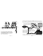
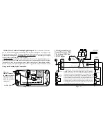
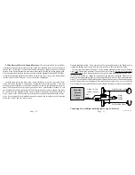
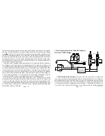
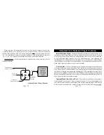
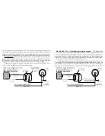
If not, use the following diagram to configure an optional relay. CAUTION! This is one
of the few uses left for a standard test light in a modern vehicle! Use a digital multimeter
(DMM) to identify the horn wire first. Probing an Airbag circuit with a standard test light
can cause the Airbag to deploy! One alternative is to disconnect the horns, then operate
the horn switch. A clicking sound from the vehicle will confirm the presence of a horn
relay. Another alternative is to check a wiring schematic of the vehicle in question.
Configuring An Optional Relay: The Brown Siren/Horn output wire has a 1 Amp
capacity, which, if exceeded, can damage the security system control module. Certain
situations, among them multiple sirens or a vehicle which lacks a horn relay, an optional
SPDT relay is required.
Page - 11
Page - 34
DLS
Relay
Relay
+
DLS Blue Wire To DS-2 Red Wire
DLS Green Wire To DS-2 Blue Wire
DLS Connector
Plugs Into Alarm
Note: Use this
diagram when
adding actuators
to a vehicle not
equipped with
factory power
door locks.
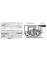
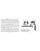
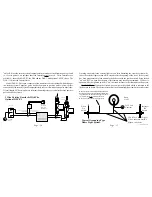
Some vehicles have a type of power doorlock system in which mechanically locking and
unlocking the driver's door will operate an electrical switch in the door which supplies
voltage to actuators in the other doors. There is no actuator in the driver's door, only a switch.
An indication of this type
of power doorlock system
is when the driver door
key will operate the pass-
enger door, but the pass-
enger side will not oper-
ate the driver door.
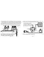
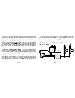
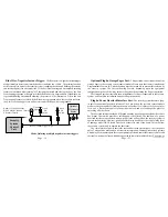
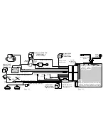
Adding The Optional DS-2 Actuator And The DLS And 2 Relays:
DLS Violet
Wire To
12 Volt
Mercedes Vacuum Doorlocks And Optional DLS-V And Two SPDT
Relays:
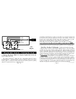
This doorlock system is used on older Mercedes Benz vehicles and consists of
electrical switches (built into pneumatic actuators) which supply 12 volts or ground to a
DLS Brown And
White Wires
Connect To
Chassis Ground
To vehicle's
horn wire.
30
86 87a 85
87
Constant
(+) 12 Volt
Brown wire
from module
(+) or (-) as
needed to operate
the Siren/Horns
Optional Relay Wiring Diagram
Содержание INSTALLATION MANUAL
Страница 2: ...Page 43 Page 2...


