1-25
OEP-3 V1 (UC)
48
Operation
Making
V
ariations of Printouts (Contin
ued)
Q1
A
4
F
:
1
S
Q1 A 4F : 1
S
*
*
*
*
SOURCE/
MEMORY
MEMORY
PAGE
CAPTURE
ALARM
POWER
Making a Printout with multiple reduced images
This subsection explains how to make printouts of multiple reduced images taking,
as an example, the making of a printout of four reduced images.
Before making the printout of four reduced images
•
Confirm the printout color quality (using, for example, the LOAD COLOR
number). (See page 93.)
•
Select the type of four-reduced image to be captured in memory. (See page 41.)
•
Select the appropriate memory page. (See page 43.)
•
Set the method to be used to capture images in the memory page and select
which image will appear after the image has been captured into memory, the
memory image or the source image. (See page 45.)
•
Select whether the white borders are to be added. (See page 54.)
You can select whether the white borders are added before or after capturing the
four reduced images in the memory.
1
Start the video source.
This operation is done using the controls of the video equipment acting as the
source.
2
3
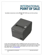
MEMORY FRM/FLD button
MOTION CHECK button
F
,
f
,
G
and
g
buttons
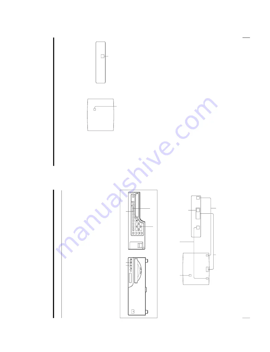
Blinks green to indicate that an
image will be captured here.
The memory page in which the
four reduced images are to be
captured.
Type of multiple reduced images to be captured
F:
Indicates that white borders are to be attached
around the images.
When white borders are attached, 4F is displayed.
When white borders are not attached, 4 is
displayed.
1:
Indicate that an image will be captured here.
Indicates that the
images from a
piece of video
equipment are
displayed on the
screen.
Indicate that an
image will be
captured here.
49
Operation
Q1
A
4
F
:
2
S
Q1 A 4F : 2
S
*
*
*
*
2
Press the CAPTURE button at the instant the image you want to print appears
on the screen.
The image has been captured in the location indicated by the green blinking
star on the video monitor screen or the position number displayed on the
printer window display in step 1.
The green blinking star (referred to as the
cursor) on the monitor video moves to the next position and the number on the
printer window display advances by 1.
At this time, the image captured in memory is displayed on the video monitor
screen. However, the image to be displayed after a few seconds depends on the
setting of AUTO LIVE in the FUNCTION SETUP menu. (See page 47.)
When INTERVAL in the PRINTER SETUP menu is set to ON, the image is
automatically captured sequentially to four positions at regular intervals. In
this case, go to step 5.
When the source image is displayed at the position where the next image is to
be captured, go to step 4.
3
Press the SOURCE/MEMORY button.
The source image appears on the video monitor screen.
4
Repeat steps 2 and 3 until you have captured four images when the memory
image remains on the video monitor screen.
Repeat step 2 until you have captured four images when the source image
appears on the video monitor screen at the next position where the image is to
be captured.
To replace a captured image
When INTERVAL is set to OFF in the PRINTER SETUP menu, you can
replace a captured image.
Example: When you want to change the image stored in the third position.
The blinking cursor moves to the next
position.
The number advances by 1.
Continue to the next page
c
Содержание OEP-3
Страница 1: ...COLOR VIDEO PRINTER OEP 3 SERVICE MANUAL Volume 1 1st Edition...
Страница 6: ......
Страница 80: ......
Страница 119: ...4 11 OEP 3 V1 UC Memory Configuration Eight Frame Memory Configuration Four Frame...
Страница 154: ......
Страница 165: ...5 11 OEP 3 V1 UC 5 5 Direct Chuck Mechanism...
Страница 176: ...2000 9 22 OEP 3 UC E 9 955 247 11...


