


Safety Check Instruction
© Celon AG
Page 7 / 9
,
Issue date: 01.09.2008
SCI.991007-1.4
Safety Check
Instruction.doc
No.
Procedure
Upper shut off limit
240
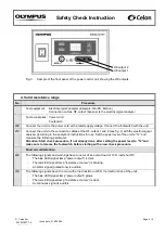
The following signals have to occur with a load resistor of 325
Ω (normal function of the unit):
-
The blue LED
(signal lamp “power output”) glows.
-
The red LED (signal
lamp “resistance too low”) is dark.
-
A high frequency continuous signal is audible.
250
The following signals have to occur with a load resistor of 450
Ω (unit does
not
shut off):
-
The blue LED
(signal lamp “power output”) glows.
-
The red LED (signal
lamp “resistance too low”) is dark.
-
A pulsed signal with a high audio frequency is audible (end of treatment).
Documentation
260
Document
the test results in “SCR.991007”.
5. High frequency leakage current (according to IEC 60601-2-2)
No.
Procedure
Test equipment:
Electrosurgical analyzer (Example: QA-ES, Metron)
Load resistor 100
Ω, 25 W (or more), 5 % tolerance, low inductive part, short time
load
Connection cables, HF-output (banana) to the electrosurgical analyzer and the load
resistor
Test accessories: Power cord
Footswitch
270
Measurement of the high frequency leakage current according to 19.3.101 a) 3) (bipolar application) as
described in IEC 60601-2-2. The output being loaded and unloaded at rated load.
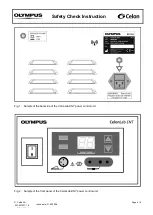
Connect the unit via the power cord with a rated supply voltage. Connect the footswitch with the unit.
280
Connect the load resistor (100
Ω) with the HF-output 1 and 2 and with the electrosurgical analyzer
according to the analyzer’s instructions for use to measure high frequency leakage currents. Set the
power level of the unit to “25” and measure the following parameter:
Attention: Start measuring, if not already done, after setting the power level
to “25”and make
sure to release the footswitch before starting with a new measurement.
290
High frequency leakage current of HF-output 1 at output load 100
Ω:
≤ 35.4 mA.
300
High frequency leakage current of HF-output 2 at output load 100
Ω:
≤ 35.4 mA.
310
Disconnect the load resistor (100
Ω) from the HF-output 1 and 2.
320
Connect the HF-
output 1 and 2 with the electrosurgical analyzer according to the analyzer’s instructions
for use to measu
re high frequency leakage currents. Set the power level of the unit to “25” and measure
the following parameter:
Attention:
Start measuring, if not already done, after setting the power level to “25”and make
sure to release the footswitch before starting with a new measurement.
330
High frequency leakage current of HF-output 1 with open output:
≤ 35.4 mA.
340
High frequency leakage current of HF-output 2 with open output:
≤ 35.4 mA.
Documentation
350
Document
the test results in “SCR.991007”.