Olympus CelonLab ENT Скачать руководство пользователя страница 5


Safety Check Instruction


©  Celon AG 

Page 5 / 9 


Issue date: 01.09.2008 

SCI.991007-1.4 

Safety Check 

Instruction.doc 

2. Display function check 

No. 

Procedure 


Test accessories:  Power cord 

060 

Connect the unit via power cord with a rated supply voltage. Switch on the unit and wait several seconds 
until the power level display shows “1”. 

070 

Press the 

“UP“-button of the power setting (increasing the power) ten times. 

The power level display has to be increased by 1 

per step until “10” (starting from “1”) is shown. 

080 

Press the 

“UP“-button of the power setting (increasing the power) and hold it down.  

The power level display has to be increased step-by-step 

until “25” is shown. 

090 

Press the 

“DOWN“-button of the power setting (reducing the power) ten times. 

The power level display has to be reduced by 1 

per step until “15” (starting from “25”) is shown. 

100 

Press the 

“DOWN“-button of the power setting (reducing the power) and hold it down.  

The power level display has to be reduced step-by-

step until “1” is shown. 


Documentation


110 

Document 

the test results in “SCR.991007”. 


3. Power output 

No. 

Procedure 


Test equipment: 

Electrosurgical analyzer (Example: QA-ES, Metron) 


Connection cables, HF-output (banana) to the electrosurgical analyzer 


Test accessories:  Power cord 


Footswitch 

120 

Connect the unit via the power cord with a rated supply voltage. Connect the footswitch with the unit. 

130 

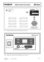
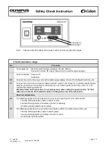
Connect the unit via the connection cables at the HF-output 1 and 2 (see fig. 3) with the electrosurgical 
analyzer according to the analyzer’s instructions for use and measure the following parameter: 

Attention: Start measuring after the display shows the appropriate value and make sure to 
release the footswitch before starting with a new measurement. 

140 

The power output at 5 (output load 100 

Ω) has to be in the range of 

4 W 

 P 

 6 W. 

150 

The power output at 10 (output load 100 

Ω) has to be in the range of 

8 W 

 P 

 12 W. 

160 

The power output at 15 (output load 100 

Ω) has to be in the range of 

12 W 

 P 

 18 W. 

170 

The power output at 20 (output load 100 

Ω) has to be in the range of 

16 W 

 P 

 24 W. 

180 

The power output at 25 (output load 100 

Ω) has to be in the range of 

20 W 

 P 

 30 W. 


Documentation


190 

Document 

the test results in “SCR.991007”. 


Содержание CelonLab ENT

Страница 1: ...maintenance take care of the different hardware versions which may be applicable see below The hardware version of the unit can be identified by the serial number which can be found on the type plate...

Страница 2: ...ountry medical device information Medizinproduktebuch 020 Labels present and legible Sample of symbol Unit is defibrillator safe Visible on the front panel see fig 2 Sample of symbol Caution Read the...

Страница 3: ...nnection for equipotential bonding Visible on the back of the unit see fig 1 Samples of label for power fuses Visible on the back of the unit see fig 1 Sample of symbol Non ionizing radiation Visible...

Страница 4: ...Celon AG Page 4 9 Issue date 01 09 2008 SCI 991007 1 4 Safety Check Instruction doc Fig 1 Sample of the backside of the CelonLab ENT power control unit Fig 2 Sample of the front panel of the CelonLab...

Страница 5: ...Documentation 110 Document the test results in SCR 991007 3 Power output No Procedure Test equipment Electrosurgical analyzer Example QA ES Metron Connection cables HF output banana to the electrosurg...

Страница 6: ...l analyzer according to the analyzer s instructions for use Set the power level of the unit to 12 and measure the following parameter Attention Start check procedure if not already done after setting...

Страница 7: ...loaded and unloaded at rated load Connect the unit via the power cord with a rated supply voltage Connect the footswitch with the unit 280 Connect the load resistor 100 with the HF output 1 and 2 and...

Страница 8: ...ety tester Example Unimet 1000 ST Bender Load resistor 100 25 W or more 5 tolerance low inductive part short time load Connection cables HF output banana to the load resistor Test accessories Power co...

Страница 9: ...c 8 Inspection label No Procedure 430 Cover or exchange an inspection label as shown below at the enclosure back of the unit and mark the due date of the next periodic safety check month year The unit...

Отзывы: