


Safety Check Instruction
© Celon AG
Page 6 / 9
,
Issue date: 01.09.2008
SCI.991007-1.4
Safety Check
Instruction.doc
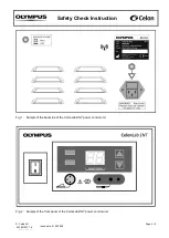
Fig. 3:
Sample of the front panel of the power control unit showing the HF-outputs.
4. Valid resistance range
No.
Procedure
Test equipment:
Electrosurgical analyzer (Example: QA-ES, Metron)
Connection cables, HF-output (banana) to the electrosurgical analyzer
Test accessories: Power cord
Footswitch
200
Connect the unit via the power cord with a rated supply voltage. Connect the footswitch with the unit.
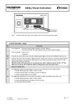
210
Connect the unit via the connection cables at the HF-output 1 and 2 (see fig. 3) with the electrosurgical
analyzer according to the analyzer’s instructions for use. Set the power level of the unit to “12” and
measure the following parameter:
Attention: Start check procedure, if not already done, after setting the power level
to “12”and
make sure to release the footswitch before starting with a new check procedure.
Short circuit detection
220
The following signals and warnings have to occur at an output load of 10
Ω (unit shut off):
-
The
blue LED (signal lamp “power output”) is dark.
-
The red LED (signal
lamp “resistance too low”) is blinking.
-
An alarm signal (pulsed tone) is audible.
230
The following signals have to occur with a load resistor of 25
Ω (normal function of the unit):
-
The blue LED
(signal lamp “power output”) glows.
-
The red LED (signal lamp “resistance too low”) is dark.
-
A continuous signal is audible.
HF-output 1
HF-output 2